Advertisement
Instruction Manual.
ACR R
A
C
ECESSED
IR
URTAIN
E
H
, A
& LPHW
LECTRICALLY
EATED
MBIENT
I
O
M
NSTALLATION AND
PERATING
ANUAL
INDEX
Section
General information ------------------------------------------------------------ 1
Dimensions ---------------------------------------------------------------------- 2
Technical Specification -------------------------------------------------------- 3
Wiring Details -------------------------------------------------------------------- 4
Installation Details -------------------------------------------------------------- 5
Servicing & Maintenance ----------------------------------------------------- 6
Spare Parts ---------------------------------------------------------------------- 7
Fault Finding --------------------------------------------------------------------- 8
Parts replacement -------------------------------------------------------------- 9
User Instructions -------------------------------------------------------------- 10
WARNINGS
1 This appliance must only be installed by a competent person in accordance with the requirements
of the Codes of Practice or the rules in force.
2 All external wiring MUST comply with the current IEE wiring regulations.
3 Warning this appliance must be earthed.
Advertisement
Table of Contents

Related Manuals for Ambirad AIRBLOC ACR Series


Summary of Contents for Ambirad AIRBLOC ACR Series
-
Page 1: Table Of Contents
Instruction Manual. ACR R ECESSED URTAIN & LPHW LECTRICALLY EATED MBIENT NSTALLATION AND PERATING ANUAL INDEX Section General information ------------------------------------------------------------ 1 Dimensions ---------------------------------------------------------------------- 2 Technical Specification -------------------------------------------------------- 3 Wiring Details -------------------------------------------------------------------- 4 Installation Details -------------------------------------------------------------- 5 Servicing & Maintenance ----------------------------------------------------- 6 Spare Parts ---------------------------------------------------------------------- 7 Fault Finding --------------------------------------------------------------------- 8 Parts replacement -------------------------------------------------------------- 9... - Page 2 Document Index. 1 Installation Requirements 5 Installation Requirements 1.1 Introduction 5.1 Mounting 1.2 General 5.2 Electrical Supply 1.3 Electrical Supply 5.3 Installation 1.3.1 Electronic Controller 5.4 Standard Controller 1.3.2 SmartElec Controller 5.5 Option SmartElec Controller 1.4 Location 5.6 LPHW only 1.5 Clearance Distance 5.7 Wiring 1.6 Health and Safety...
-
Page 3: General Information
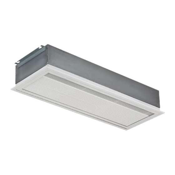
General Information 1.1 Introduction This instruction manual describes the Airbloc ACR Recessed range of air curtains. Models range from 1000mm to 2000mm in length, in both Standard and High capacity and are available in either Electrically heated, Ambient or LPHW. They are designed for discreet positioning in a suspended ceiling or bulkhead in the doorways of retail or commercial premises. - Page 4 BMS control, time switches, room thermostats and 1.5 Clearance distances door interlocks can be installed at the discretion and responsibility of the installer. It is recommended that a minimum clearance of 100mm is allowed around the case sizes detailed All unit must be wired in accordance with I.E.E below.
-
Page 5: Dimensions
2. Dimensions. 2.1 ACR Air Curtain DIM 'C' DIM 'F' DIM 'G' Air outlet Air inlet DIM 'B' Dimensional detail (mm) ACR100SE6/9; ACR150SE12; ACR200SE18; ACR120HE12; ACR180HE18; Size ACR100SW9; ACR150SW12; ACR200SW18; ACR120HW12; ACR180HW18; ACR100SA ACR150SA ACR200SA ACR120HA ACR180HA 1220 1520 2020 1185 1785 1182... - Page 6 87.0 2.2 Electronic Controller 60.3crs 13.35 60.3crs Fig.3. Surface mount Cable Entries 75.0 SELECT 60.3crs 7.35 Fig.4. flush mount Earthing Cable point Entries 2.3 Optional SmartElec Controller dimensions 80 crs Earthing Cable point Entry 4 Holes Ø5mm...
-
Page 7: Technical Specification
3. Technical Specification. ACR100SE6 ACR100SE9 ACR150SE12 ACR200SE18 General Data Maximum height Heat medium Electric heated Total heat Heat setting Heat setting 3 / 6 4.5 / 9 6 / 12 9 / 18 Fan type Crossflow Fan dia Fan settings Air outlet Fixed Switching type... - Page 8 ACR120HE12 ACR180HE18 General Data Maximum height Heat medium Electric heated Total heat Heat setting Heat setting 6 / 12 9 / 18 Fan type Crossflow Fan dia Fan settings Air outlet Fixed Switching type Remote switchbox / SmartElec Weight 38.0 55.0 Electrical Data Maximum heat capacity...
- Page 9 ACR100SA ACR150SA ACR200SA General Data Maximum height Heat medium Ambient Fan type Crossflow Fan dia Fan settings Air outlet Fixed Switching type Remote switchbox Weight Electrical Data Supply voltage 230V 1ph 50Hz Total load Cable size 2 x 0.75mm² + Earth External fuse size amps A/pha Motor power...
- Page 10 ACR120HA ACR180HA General Data Maximum height Heat medium Ambient Total heat Heat setting Heat setting Fan type Crossflow Fan dia Fan settings Air outlet Fixed Switching type Remote switchbox Weight 40.0 58.0 Electrical Data Maximum heat capacity Supply voltage 230V 1ph 50Hz Total load Starting Current Low speed amps...
- Page 11 ACR100SW9 ACR150SW12 ACR200SW18 General Data Maximum height Heat medium LPHW Maximum heat capacity Heat setting Heat setting Fan type Crossflow Fan dia Fan settings Air outlet Adjustable vent Switching type Remote switchbox Weight Electrical Data Maximum heat capacity Supply voltage 230V 1ph 50Hz Total load Cable size...
- Page 12 ACR120HW12 ACR180HW18 General Data Maximum height Heat medium LPHW Total heat Heat setting Heat setting Fan type Crossflow Fan dia Fan settings Air outlet Fixed Switching type Remote switchbox Weight 40.0 58.0 Electrical Data Maximum heat capacity Supply voltage 230V 1ph 50Hz Total load Starting Current A/pha...
- Page 13 Electronic Controller General Data Sensor input Control Setpoint 16 to 35 ºC in steps of 1 degree Temperature Control Proportional with 1ºC hysteresis Minimum Power 30% to 99 % Cycle time 0.3 seconds fixed Protection 2 x high speed fuse for the protection of the heater switching devices Fan Output 3 off Relay for High, Medium and Low Fan setting 3A max 240Vac...
- Page 14 4. Wiring Diagrams. Installer Wiring - Electrically Heated 9 & 12kW ONLY The program panel is connected to the base unit via a set of 3 way connectors marked "+12V”, “DATA” and “GND". Interconnecting wiring is via Belden cable as shown. Max length 50m. It is recommended that this control cable is run separately within its own trunking to avoid external interference.
- Page 15 Installer Wiring - Electrically Heated 18 & 24kW ONLY The program panel is connected to the base unit via a set of 3 way connectors marked "+12V”, “DATA” and “GND". Interconnecting wiring is via Belden cable as shown. Max length 50m. It is recommended that this control cable is run separately within its own trunking to avoid external interference.
- Page 16 Installer Wiring - Ambient The program panel is connected to the base unit via a set of 3 way connectors marked "+12V”, “DATA” and “GND". Interconnecting wiring is via Belden cable as shown. Max length 50m. It is recommended that this control cable is run separately within its own trunking to avoid external interference.
- Page 17 Installer Wiring - LPHW The program panel is connected to the base unit via a set of 3 way connectors marked "+12V”, “DATA” and “GND". Interconnecting wiring is via Belden cable as shown. Max length 50m. It is recommended that this control cable is run separately within its own trunking to avoid external interference.
- Page 18 Factory Wiring - Electrically heated 9 & 12kW ONLY SENSOR DATA DOOR +12V THERMAL Overheat Elements Fan Motor Terminal Description The element output is connected to the right and left side of each terminal block marked "AC1-T1”, “AC2-T1”, AC1/2-T1 Heater Elements phase 1 AC1-T2”, “AC2-T2”, “AC1-T3”...
- Page 19 Factory Wiring - Electrically heated 18 & 24kW ONLY SENSOR DATA DOOR +12V THERMAL Overheat Elements Elements Fan Motor Terminal Description AC1/2-T1 Heater Elements phase 1 415V 50Hz AC1/2-T2 Heater Elements phase 2 Mains Supply AC1/2-T3 Heater Elements phase 3 THERMAL Thermal Overheat trip 0v Terminal...
- Page 20 Factory Wiring - Ambient SENSOR DATA DOOR +12V THERMAL Fan Motor Terminal Description The fan output is connected to a 4 way connector Neutral to fan marked "N”, “F1”, “F2” and “F3". Fan - low speed Fan - medium speed Fan - high speed...
- Page 21 Factory Wiring - LPHW SENSOR DATA DOOR +12V THERMAL Overheat 3 Port Valve Fan Motor Terminal Description The fan output is connected to a 4 way connector Neutral to fan marked "N”, “F1”, “F2” and “F3". Fan - low speed The thermal trip is connected to a 2 way connector marked "THERMAL"...
- Page 22 Network Wiring - Electronic controller PROGRAM PANEL (rear view shown) DATA +12V Screw terminals DATA +12V Networking This diagram refers only to the data cable wiring of 2 or more networked air curtains. (maximum BASE UNIT 6 air curtains per control panel). (located in air curtain 1) For mains wiring refer to section 4 of this manual ‘installer wiring...
- Page 23 4.10 Installer wiring diagram Electrically Heated with SmartElec control. PROGRAM PANEL (rear view shown) Interconnecting Wiring The program panel is connected to the base unit via a set of 4 way re- movable connectors marked "7V”, “0V”, “B” and “A". Interconnecting wiring is via 2 pairs of Belden 8132 cable as shown in the table below.
- Page 24 4.11 Factory installed wiring. Electrically Heated with SmartElec control. ϑ Sensor Overheat BASE UNIT Trip (located in air curtain) Md Hi Fan Motor The heater output is connected to the right hand side of Terminal Description each terminal block marked "Load1", "Load2" and "Load3". Load1 Heater phase 1 Load2...
- Page 25 4.12 Network wiring Electrically Heated SmartElec control.
-
Page 26: Installation Details
5. Installation Details. 5.1 Mounting use. The unit should be wired in accordance with IEE Regulations for the Electrical Equipment of Buildings. Airbloc units should be installed horizontally directly over the door opening. It is recommended that the air curtain is installed on the inside of the 5.3 Installation. - Page 27 Step 3 Step 6 Access to the inside of the air curtain grille can be Either drop rods or catenary wire (available from made. Open the grille. The grille is hinged to manufacturer) can be used to fasten the air curtain prevent the inner frame from dropping.
- Page 28 adjusting the height to ensure that the grille sits Installation details Option flush to the ceiling (when re-fitted) take the grille SmartElec Controller assembly and refit using the screws removed during Step 5. The SmartElec base unit is pre-installed inside the air curtain.
- Page 29 5.6 Installation details - LPHW Only Test product as shown in the User Instructions. 5.7 Installation wiring With the grille open, the heating coils are mounted With case removed, connect the electrical supply and program panel interconnecting wiring to the as shown below.
-
Page 30: Servicing & Maintenance
6. Servicing & Maintenance. ALWAYS ENSURE THAT MAIN Using a pozidrive screwdriver remove the M5 EXTERNAL ELECTRICITY SUPPLY screws at the side of the grille. SWITCHED OFF BEFORE COMMENCING ANY MAINTENANCE ON THIS HEATER. To obtain the best results from the heater, it is essential to avoid the accumulation of dust and dirt within the unit on the air inlet and discharge grilles. -
Page 31: Spare Parts
7. Spare parts 7.1 General ACR100SE6/ ACR150SE12/ ACR200SE18/ ACR120HE12/ ACR180HE18/ ACR100SE9/ Description ACR150SW12 ACR200SW18 ACR120HW12 ACR180HW18 ACR100SW9/ /ACR150SA /ACR200SA /ACR120HA /ACR180HA ACR100SA Motor 100003 100003 100012 100535 100535 Relay 900000 900000 900000 900078 900078 Rotor 100010 100541 100001 100006 100010 Left Hand Rotor 100536... - Page 32 7.2 SmartElec controller Due to the nature of it’s construction, it is not advisable to repair damaged electronic components on either the SmartElec base unit or Program panel. ACR100SE9/ ACR150SE12/ ACR200SE18/ ACR120HE12/ ACR180HE18/ Description ACR100SW9 ACR150SW12 ACR200SW18 ACR120HW12 ACR180HW18 Program 900306 900306 900306...
-
Page 33: Fault Finding
8. Fault Finding. temperature alarm. 8.1 General If the air curtain does not operate after running through the detail provided in Section 6, then a suitably competent service engineer should be called to identify the nature of the fault. Note The manufacturer operates a service function from the address provided in these instructions. - Page 34 1: Polarity: Use a multimeter to check correct b) Check the tightness of the cables in the polarity between all 4 cores i.e. that 0v goes to 0v, plugs. c) Check that the plugs are fitted to the 7v goes to 7v, A to A, and B to B. correct circuit board pins.
-
Page 35: Parts Replacement
9. Parts replacement. 9.1.1 Electrical element replacement 9.1.2 Electrical element replacement Step 1 Using a pozidrive screwdriver remove the Step 1 Using a pozidrive screwdriver undo screws M5 screws at the side of the grille. Access to the securing the grille and remove. Remove 4 screws inside of the air curtain grille can be made. - Page 36 9.2.1 Rotor and motor replacement SE Step 5 Disconnect rotor from motor shaft. Step 1 Using a pozidrive screwdriver remove the M5 screws at the side of the grille. Access to the inside of the air curtain grille can be made. Open the grille.
- Page 37 9.2.2 Rotor and motor replacement HE Step 6 Remove the bolts securing the motor to the Step 1 Using a pozidrive screwdriver undo screws chassis. securing the grille and remove. Remove 4 screws securing the top of the case and remove. Slacken two hinging bolts on both ends.
-
Page 38: User Instructions
10. User Instructions. fig.11. Electronic Controller 10.1 Keypad button will allow you to navigate. button will allow you to increase the setting. button will allow you to decrease the setting. 10.2 Operation On first power up, the display panel will have the following default settings: F. - Page 39 The next parameter will either turn the unit On or Off. To turn the unit Off, press the button. ‘On’ will start flashing. Press the button. ‘Off’ will start flashing. Press the button to confirm new setting. To turn the unit On, press the button.
- Page 40 If you have previously pressed the button, setting ‘A’ will appear. This setting will enable the Auto Mode. (Range: On/Off) To alter the setting, press the button then the buttons to increase/decrease the desired setting. Press the button to confirm new value. The Auto Mode display will remain until cancelled by following this procedure in reverse.
- Page 41 10.4 Option SmartElec Controller fig.12. SmartElec 10.3.1 Keypad button will allow you to navigate. button will allow you to increase the setting. button will allow you to decrease the setting. 10.3.2 Operation When power is applied to the controller, the display will illuminate with the air outlet sensor temperature.
- Page 42 Pressing the button again will advance the display to the FAN setting (default = ‘F’ 1 ). This is denoted by the prefix ‘F’ followed by either a ’0’ for FAN (UNIT) OFF, ‘1’ for LOW FAN, ’2’ for MEDIUM FAN or ’3’ for HIGH FAN (default = ‘F 2’ ). Use the buttons to increase/decrease the desired setting.
- Page 43 Notes.
- Page 44 Brierley Hill West Midlands DY5 1QA United Kingdom. Telephone 01384 489700 Facsimile 01384 489707 Email marketing@airbloc.co.uk Website www.airbloc.co.uk Airbloc is a registered trademark of AmbiRad Limited. Because of continuous product Technical Support www.s-i-d.co.uk innovation, AmbiRad reserve the right to change product specification without due notice.
Need help?
Do you have a question about the AIRBLOC ACR Series and is the answer not in the manual?
Questions and answers