
Subscribe to Our Youtube Channel
Related Manuals for LNS ALPHA 538


Summary of Contents for LNS ALPHA 538
- Page 1 ALPHA 538 / 552 BARFEED Instruction Manual For CNC machine tool peripherals, it’s LNS , then all the rest 9.X51.01.US...
-
Page 3: Table Of Contents
ELECTRICAL EQUIPMENT ....................4-2 ELECTRICAL CABINET ......................4-5 ELECTRICAL DIAGRAMS ....................4-12 INTERFACE ......................... 4-18 CHAPTER 5 : PNEUMATICS ................5-1 PNEUMATICAL EQUIPMENT ....................5-2 F.R.L. UNIT ..........................5-3 PNEUMATIC VALVE BATTERY .................... 5-4 MAINTENANCE ........................5-6 PNEUMATIC DIAGRAMS ...................... 5-7 ALPHA 538/552... - Page 4 OPERATION PARAMETERS ....................8-8 AUTOMATIC CYCLE......................8-19 POWERING OFF ........................8-19 CHAPTER 9 : MALFUNCTIONS ............... 9-1 ALARMS ..........................9-2 FACTORS AFFECTING PERFORMANCE ................9-14 MAINTENANCE ........................9-16 CHAPTER 10 : APPENDICES ................. 10-1 PROGRAMMING EXAMPLE ....................10-2 ORDERING FORM .......................10-3 LNS WEB ADRESSES ......................10-4 ALPHA 538/552...
-
Page 6: Chapter 1 : Basic Notions
CHAPTER 1: BASIC NOTIONS CHAPTER 1 : BASIC NOTIONS ALPHA 538/552... -
Page 7: Structure
(see chapter *) or (see point *). 1.2. Captions Whenever possible, the reference numbers contained in the instruction manual are shown with the LNS ordering number of the indicated element. To make it easier to place an order of supplies, a form has been included in the annex at the end of this manual. -
Page 8: Rights
LNS SA. LNS SA and its subsidiaries cannot be held responsible for damage and problems arising from the use of options and products other than LNS products, or products approved by LNS SA. -
Page 9: Declaration Of Compliance
- Concerning the EMC Directive : · EN 61000-6-4 : Generic emissions standard, Industrial environment · EN 61000-6-2 : Generic immunity standard, Industrial environment Place and date : Seal and signature : Orvin, the 4 December 2012 Mrs. Nadia Pellaton Manager Export department ALPHA 538/552... -
Page 10: Safety Instructions
All persons who perform work on this machine must have read and understood the instructions and installation notice. LNS disclaim all responsibility for possible accidents or property damage caused when safety instructions are not followed. · Do not handle the machine without having ·... -
Page 11: Safety Analysis For A Correct Incorporation
ALPHA 538/552 is integrated; its association with other equipment, People’s interaction with the machine. · Evaluate and assess the risks associated by using the machine ALPHA 538/552: programming risks operation risks risks of use maintenance risks ·... -
Page 12: Chapter 2 : Technical Data
CHAPTER 2: TECHNICAL DATA CHAPTER 2 : TECHNICAL DATA ALPHA 538/552... -
Page 13: Characteristics
(square: 4 mm) (square: 4 mm) (square: 4 mm) (profiled: on flats) (hex: 5 mm) (hex: 5 mm) (hex: 5 mm) ALPHA 538: 42 mm Maximum diameter ALPHA 552: 52 mm Minimum bar stock length 1000mm Maximum bar stock length 3200 mm... - Page 14 CHAPTER 2: TECHNICAL DATA ALPHA 538/552...
-
Page 15: Layout Of The Elements
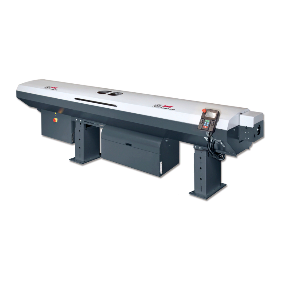
Chain drive with Smart Power Booster Remnant retract device Hydraulic tank with remnant tray Main switch Electrical cabinet Main access cover Pneumatic front rest Loading ramp Bar length measuring device (not visible) Front stand Retraction system Rear stand Pneumatic assembly ALPHA 538/552... -
Page 16: Chapter 3 : Setting Into Operation
CHAPTER 3: SETTING INTO OPERATION CHAPTER 3 : SETTING INTO OPERATION ALPHA 538/552... -
Page 17: Transportation
Please read the safety precautions described at the beginning of this manual before handling the following devices. Depending on its destination, the ALPHA 538/552 bar feeder may be delivered either on a pallet or packed in a wooden crate. When transported by sea or by air, the second solution is recommended. - Page 18 CHAPTER 3: SETTING INTO OPERATION From this point on, the bar feeder is unpacked in the same way as when delivered on a pallet. The ALPHA 538/552 bar feeder is always delivered as follows: · A pusher and guiding elements set is mounted in the bar feeder (A). Depending on the purchase order, other sets may be delivered in a separate box.
- Page 19 CHAPTER 3: SETTING INTO OPERATION 1.2. Preparation for mounting For mounting and installing the bar feeder, it is advisable to contact LNS or one of its agents. The latter cannot be held responsible for any malfunction resulting from an incorrect installation in which they did not take part.
-
Page 20: Mounting
The alignment may be carried out using a nylon string, an optical tool, etc. If you do not have any alignment tools, please contact LNS or their local representative so they may take care of the bar feeder installation. -
Page 21: Anchoring To The Ground
8 anchorage bolts (B) must be furnished by the client (min. M10 x 100 mm / 1/2" x 4"). Once the anchoring bolts are tightened, check the alignment again, and correct it if necessary. · Tighten the nuts of the leveling screws. · Remove the 4 (2+2) shipping screws for the retraction system (C). ALPHA 538/552... -
Page 22: Electrical Connections
Transformer T1 Hydraulic pump motor The LNS bar feeders are equipped with their own thermal protection systems (breakers, thermal relays and fuses, etc.). The power supply for the bar feeder should be connected to the output of a breaker mounted in the electrical control box of the lathe (10 A max.). -
Page 23: Pneumatic Connections
To increase the pressure, turn it clockwise. To decrease it, turn it in the opposite direction. The operational pressure should be set at 5 bar. When the settings are done, lock the adjuster by pushing it downward. ALPHA 538/552... -
Page 24: Hydraulic Connections
CHAPTER 3: SETTING INTO OPERATION HYDRAULIC CONNECTIONS The guiding concept of the ALPHA 538/552 bar feeder consists mainly in maintaining the bar suspended in an oil bath. This reduces friction of the turning bar stock, and dampens the vibration generated by the bar stock. -
Page 26: Chapter 4 : Electrics
CHAPTER 4: ELECTRICS CHAPTER 4 : ELECTRICS ALPHA 538/552... -
Page 27: Electrical Equipment
Please read the safety instructions provided at the beginning of this manual before handling the following devices. Particular attention should be given to the handling of electrical elements because of risks of electrocution. In case of possible electrical malfunctions, it is advisable to contact LNS or their local representative. 1.1. Description The electrical parts of the bar feeder, as well as the diagrams representing them, conform to the CEI 204- 1 EN 607 international electrical codes. - Page 28 Front rest reference (option) SQ 13 B18120401 Front rest pulse signal (option) SQ 14 C11111100 Inserting clutch off (option) SQ 15 C11111100 Inserting clutch on (option) SQ 16 C11111100 Material extraction (option) SQ 17 C11111100 Material inserting (option) ALPHA 538/552...
- Page 29 Particular attention should be given to the handling of electrical elements because of risks of electrocution. In case of possible electrical malfunctions, it is advisable to contact LNS or their local representative. It is strictly prohibited to make adjustments as long as the bar feeder is under electrical power.
-
Page 30: Electrical Cabinet
B66000007 Safety restart relay (CE version) 4.932 Hydraulic pump motor M1 contactor B19110100 Circuit breaker 4.503 Main circuit breaker 2,5 to 4 A B55000003 Main disconnect switch Transformer 1-ph (Optional, not shown here) B25120020 24 VDC Power supply ALPHA 538/552... - Page 31 (C). At the factory, the breaking current is set to 2.5 amperes. TEST Designation Description Power in connecting terminal Breaking current setup Release button Power out connecting terminal Test button ALPHA 538/552...
- Page 32 The incoming power must be connected to the Primary Terminal Block. Use the contacts corresponding to the supplied power (346V AC to 440V AC, see drawing below). The outgoing power is always connected to the 220VAC terminals of the Secondary Terminal Block. Secondary terminal block Primary terminal block ALPHA 538/552...
- Page 33 220V AC input terminals 24V DC output terminals PCB (Printed Circuit Board) PCB is a board with circuit printed and electrical components welded on the surface. It offers sockets and terminals for electrical components like relays, cables and fuses. ALPHA 538/552...
- Page 34 DO NOT TOUCH, MAY BE VERY HOT AND CAUSE SERIOUS PERSONNEL INJURY. I/O interface (CN1) Used to connect host controller (PLC) or control I/O signal. Serial communication interface (CN2) Used to connect other controllers Ground terminal ALPHA 538/552...
- Page 35 The program loaded into the PLC manages this information. The PLC then distributes the interface signals, controls the SERVO drives as well as the pneumatic valves, and displays the appropriate messages on the remote control station. ALPHA 538/552...
- Page 36 <Not in use> <Not in use> D+/D- COM3/COM2 +24V/24 <Not in use> DC out <Not in use> <Not in use> <Not in use> <Not in use> <Not in use> Clamping device signal Lathe in auto cycle Feed order Push order ALPHA 538/552...
-
Page 37: Electrical Diagrams
CHAPTER 4: ELECTRICS 4-12 ELECTRICAL DIAGRAMS ALPHA 538/552... - Page 38 CHAPTER 4: ELECTRICS 4-13 ALPHA 538/552...
- Page 39 CHAPTER 4: ELECTRICS 4-14 ALPHA 538/552...
- Page 40 CHAPTER 4: ELECTRICS 4-15 ALPHA 538/552...
- Page 41 CHAPTER 4: ELECTRICS 4-16 ALPHA 538/552...
- Page 42 CHAPTER 4: ELECTRICS 4-17 TP04 = Asia market ALPHA 538/552...
-
Page 43: Interface
The voltage of the bar feeder is indicated on the identification plate (A). 4.1. Description The interface cable(s), between the bar feeder and the lathe, are provided by LNS. The diagram for the interface corresponding to your device, essential when making the electrical connection, is located inside the electrical cabinet. - Page 44 Transformer T1 Hydraulic pump motor The LNS bar feeders are equipped with their own thermal protection systems (breakers, thermal relays and fuses, etc.). The power supply for the bar feeder should be connected to the output of a breaker mounted in the electrical control box of the lathe (10 A max.).
- Page 45 (14) Options The options described below are an integral part of the standard equipment of the LNS bar feeders. These signals, however, are not required for the proper operation of the devices, or the safety locking for protecting persons and materials. The options are available only to optimize production conditions.
-
Page 46: Chapter 5 : Pneumatics
CHAPTER 5: PNEUMATICS CHAPTER 5 : PNEUMATICS ALPHA 538/552... -
Page 47: Pneumatical Equipment
1.2. Layout of the pneumatic elements Designation Description Air filtering unit with air pressure switch Valve battery Front rest with air blast Material clamping system Bearing blocks opening/closing pneumatic cylinders Material dropping pneumatic cylinder Protection switch SQ1 pneumatic cylinder Bar stock selection ALPHA 538/552... -
Page 48: Unit
Unlock the adjusting knob by pulling it upward. To increase the pressure, turn it clockwise. To decrease it, turn it in the opposite direction. The operational pressure should be set at 5 bar. When the settings are done, lock the adjuster by pushing it downward. ALPHA 538/552... -
Page 49: Pneumatic Valve Battery
Material clamping C11110100 Material loading (bar selection) C11110100 Material dropping fingers C11110100 Air blast C11110100 Front rest opening/closing C11110100 Smart booster clutch engage/disengage YV10 C11110100 Smart booster bar insert/extract YV11 <Reserved> YV12 C11110100 Remnant ejection C11121400 Air pressure switch ALPHA 538/552... - Page 50 2. Set the difference range on screw B. (17) Valves Contact your LNS agent for further safety information before proceeding to any operation on the valves. By pressing the button A, the cylinders can be activated manually. This button can be kept at the activation position by pressing it down and turning 90°...
-
Page 51: Maintenance
For the best performance, the oil should drop every cylinder operation. Adjust the fluent with auxiliary of channel open button. Let the oil drop once after pressing the “channel open” button for 10 times. · Connect the air inlet tube and turn air source on. ALPHA 538/552... -
Page 52: Pneumatic Diagrams
CHAPTER 5: PNEUMATICS PNEUMATIC DIAGRAMS ALPHA 538/552... - Page 53 CHAPTER 5: PNEUMATICS ALPHA 538/552...
- Page 54 CHAPTER 5: PNEUMATICS ALPHA 538/552...
- Page 55 CHAPTER 5: PNEUMATICS 5-10 ALPHA 538/552...
-
Page 56: Chapter 6 : Hydraulics
CHAPTER 6: HYDRAULICS CHAPTER 6 : HYDRAULICS ALPHA 538/552... -
Page 57: Hydraulic Equipment
A level allows the monitoring of the filling rate of the hydraulic tank. 1.2. Layout of the elements M1 / SP2 Designation Article No Description C17110500 Level Guiding blocks supply tube (not shown here) Front rest supply tube C17120400 Drain plug X51.09.P017A Hydraulic pump motor 44.0179.K0.15 Oil pressure control switch ALPHA 538/552... -
Page 58: Description Of The Elements
Turning in the opposite direction, will produce the reverse. PLC input X12 will show the condition of the switch, and can be monitored to assist for setting. 3. When the adjustment is completed, reinstall the cap screw into the plug and tighten (C). ALPHA 538/552... -
Page 59: Maintenance
· Refill new oil into the bar feed system until the indicator shows oil level at H (about 25 liters needed). Confirm there is no leaking from the plug. · Install the remnant tray back. Dispose of waste used oil properly in an environmentally friendly way, and according to your local regulation. ALPHA 538/552... -
Page 60: Chapter 7 : General Description
CHAPTER 7: OPERATION CHAPTER 7 : GENERAL DESCRIPTION ALPHA 538/552... -
Page 61: Bar Magazine
Please read the safety instructions provided at the beginning of this manual before handling the following devices. 1.1. Description The barfeed ALPHA 538/552 is equipped with an internal, gravity-fed loading ramp. Depending on the length of the bar feeder (3M, 12', 4M), the bar magazine may include six or seven supports. - Page 62 (B) can be moved. 2. Move the setup handle (B) to the desired diameter range, corresponding to the bar stock diameter to be loaded. 3. Lock the side handle (A) completely, so that the setup handle (B) cannot be moved. ALPHA 538/552...
-
Page 63: Guiding Elements
2.2. Layout of the elements (*) Designation Description Upper guiding element "Quick Change" holding system for the upper guiding elements Oil supply Lower guiding element Locking system Front rest guiding elements* (*) Some elements are explained in more details in the following paragraphs. ALPHA 538/552... - Page 64 Left to Right: X51.31.A211A.xx Right to Left: X51.31.A211A.xx X51.31.A004A/xx X51.31.A005A.xx (2x) (2x) (6x) (10x) Left to Right: X51.31.A213A.xx X51.31.A00 Right to Left: X51.31.A213A.xx X51.31.A004A/xx X51.31.A005A.xx X51.07.A003A.xx 3A.xx (11x) (7x) Left to Right: X51.31.A215A.xx Right to Left: X51.31.A215A.xx X51.31.A004A/xx X51.31.A005A.xx ALPHA 538/552...
- Page 65 2.6. Guiding element locking system For guiding elements with diameter over 43mm, a pin is added to avoid the guiding element to stick to the pusher. Guiding element Guiding element locked unlocked ALPHA 538/552...
-
Page 66: Pusher
Depending on the spindle length, 2 pusher lengths are available: Pusher length (LP) ±1 Useable length (Lu) ±1 Pusher version Cone Collet Cone Collet Standard 1596 mm 1554 mm 1220 mm 1178 mm Long 1876 mm 1834 mm 1500 mm 1458 mm Cone Collet ALPHA 538/552... - Page 67 014.021.013 052.015.434 052.015.1524 014.021.013 15053/40-xx.xx 052.015.444 052.015.1534 014.021.013 052.015.454 052.015.1544 014.021.013 15053/42-xx.xx 052.015.464 052.015.1554 014.021.013 052.015.474 052.015.1564 014.021.013 052.015.484 052.015.1574 014.021.013 15053/45-xx.xx 052.015.514 052.015.1604 014.021.013 15053/48-xx.xx 052.015.534 052.015.1624 014.021.013 15053/50-xx.xx 052.015.544 052.015.1634 014.021.013 15053/50-xx.xx 052.015.554 052.015.1644 014.021.013 15053/52-xx.xx ALPHA 538/552...
- Page 68 Stretched Retracted Article No Internal ø Retracted length Maximum Stroke 042.037.013 48mm 178mm 384mm 042.037.073 42mm 240mm 580mm 332.037.053 42mm 225mm 530mm 332.037.023 42mm 165mm 348mm ALPHA 538/552...
-
Page 69: Synchronization Device
7-10 SYNCHRONIZATION DEVICE The barfeed ALPHA 538/552 uses an electronic synchronization that is directly connected to the lathe to measure the movements of the sliding headstock and replicate them to the pusher. This prevents the small bar stock to be bent during the spindle movements. -
Page 70: Chain Drive
· With a torque wrench, apply a torque on the side screw (C) according to following chart). Chain tension 0.5 Nm 0.5 Nm 0.5 Nm · When done, tighten the lock screws (A) of the adjusting bearing (B). ALPHA 538/552... -
Page 71: Remnant Extraction System
The vise of the ALPHA 552 bar feeder allows the extraction of remnants of from 90mm to 400 mm long. 6.2. Layout of the elements Designation Article No. Description Bar stock clamping device X51.22.P010C Remnant extraction clamping blades Remnant extraction drawer X51.22.P016B Remnant extraction help ALPHA 538/552... - Page 72 Install the new blade according to the drawing below, and secure them with the fastening screws Designation Article No. Description X51.22.P010C Remnant extraction clamping blades C11130400 Adjustment for lifting of the extraction cylinder C11130400 Adjustment for lowering of the extraction cylinder ALPHA 538/552...
-
Page 73: Pneumatic Front Rest
PLC. A cover (A) protects the mechanism, and an oil pan (D) collects the oil. 7.2. Layout of the elements Designation Description Cover Air blast 2 Guiding elements Pneumatic cylinder Oil pan Setting of the front rest opening ALPHA 538/552... - Page 74 Pull the lever (A) to unlock the stopper nut (B). · Turn the stopper nut to adjust the position. · Turn the flat face of the stopper nut to horizontal position. · Lower the lever (A) to lock the stopper nut (B). ALPHA 538/552...
-
Page 75: Retraction Device
To facilitate these tasks, the ALPHA 538/552 can be equipped with a retraction system, which allows the operator to move the bar feeder. The rigidity of the system guarantees a perfect alignment when the bar feeder is in working position. -
Page 76: Chapter 8 : Operation
CHAPTER 8: OPERATION CHAPTER 8 : OPERATION... -
Page 77: Controls
CHAPTER 8: OPERATION CONTROLS 1.1. Remote control The remote control offers a touch screen display and buttons for operating the bar feed system when it’s in MANUAL mode. 1.2. Display ALPHA 538/552... - Page 78 NOT at home position. · the channel is open, the pusher is at home position and the measurement device in upper position (sensor SQ1 ON). Rightward Move pusher rightward. Only available when the bar feeder is in MANUAL mode. ALPHA 538/552...
- Page 79 · Channel close and the pusher charges forward for insertion. To operate this button, the following conditions must be fulfilled: · The bar feeder is in MANUAL mode · The pusher is at home position (sensor SQ2 ON) ALPHA 538/552...
-
Page 80: Powering On
0. Take any approach below to reset the original position: Move the pusher back to home position. Power the bar feeder OFF and ON. Move the pusher back to home position. Pressing the button leftward for 3 seconds. ALPHA 538/552... -
Page 81: Emergency Stop Button
When the emergency situation is fixed, release the emergency stop button and press the manual key on the remote control to restart the bar feeder. Emergency stop button on the cabinet STP1 INTERRUPTION RESET Emergency stop button on the remote control STP2 INTERRUPTION RESET ALPHA 538/552... -
Page 82: Automatic Sequence
4. The bar feeder channel is closed and pusher is not at origin reference. Manually move the pusher forward until the bar stock pushes against the stopper. Close the lathe chuck. Switch the bar feeder into AUTOMATIC mode. Switch the lathe into AUTOMATIC mode. ALPHA 538/552... -
Page 83: Operation Parameters
The lathe must place a stopper inside the lathe for positioning. Example: If the part is 100mm and the cut off tool width is 3mm. The value entered here is 100+3=103. ALPHA 538/552... - Page 84 This parameter has to be deactivated if a stopper is used to positioning the bar stock. 5.3. Application parameters Application: Part feed out with turret Defines if the lathe turret waits in position or follows the bar stock displacement during feeding operation. ALPHA 538/552...
- Page 85 This positioning corresponds to a value (Z) programmed by the operator, which is equal to the distance between the measuring cell and the position of the material in the lathe clamping device. With this system, the setting is the same for any bar length. ALPHA 538/552...
- Page 86 The procedure is the same as this for the end of bar setting. 5.5. Torque parameters Torque: Torque values as described. 5.6. Language parameter Language Allows the user to choose the barfeed HMI language. ALPHA 538/552...
- Page 87 Allows to choose units of measure. Misc: Functions Unload bar stock, Dry run and front rest setup functions are available on this screen. Misc: Function – Unload bar stock Unload bar stock function Misc: Dry Run Dry run function ALPHA 538/552...
- Page 88 5.8. Service parameters (Password protected, only for trained technician) Service: Main screen Main screen SERVICE: Bar feeder setup Defines the Bar feeder length and loading position. SERVICE: Bar feeder setup Defines the pusher length, the use of extraction device and the loading cycle configuration. ALPHA 538/552...
- Page 89 SERVICE: Torque & feed rate Without bar stock Pusher feed rate without bar stock With clamping device closed Pusher torque with clamping device closed SERVICE: Torque & feed rate 2 Default values insertion/extraction: 100% Default value Booster servo: 300% ALPHA 538/552...
- Page 90 CHAPTER 8: OPERATION 8-15 SERVICE: Feed rate Feed rate values. SERVICE: Feed rate 2 Feed rate values. SERVICE: Options setup Defines the front rest type, if the bar feeder uses a synchronization system and allows to choose booster options. ALPHA 538/552...
- Page 91 PI19: R3 turns on at EOB and turns off at Loading Start / in top cut position PI46: A4 signal NC/NO SERVICE: Clamping device Delay between signal activation and mechanical accomplished status. SERVICE: additional I/O module Additional inputs for specific functions. ALPHA 538/552...
- Page 92 5.9. HELP To reach the Help menu, press the STOP button, then press "?". HELP: Software versions Shows PLC and HMI installed software versions. HELP: Interface signals Shows signals and their status. Grey = not active Red = active ALPHA 538/552...
- Page 93 8-18 HELP: Inputs Shows Inputs and their status. Grey = not active Red = active HELP: Outputs Shows Outputs and their status. Grey = not active Red = active HELP: End of bar Cycles Number of EOB cycle. ALPHA 538/552...
-
Page 94: Automatic Cycle
When powering off the barfeed, make sure the pusher is in reference position, lifted up and no bar stock is present in the guiding element. To power down, turn the switch to the left, to the 0off position. ALPHA 538/552... - Page 95 CHAPTER 8: OPERATION 8-20 ALPHA 538/552...
-
Page 96: Chapter 9 : Malfunctions
CHAPTER 9: MALFUNCTIONS CHAPTER 9 : MALFUNCTIONS ALPHA 538/552... -
Page 97: Alarms
Solutions Put back the bar feeder in working position. Check the SQ10 switch. Press the STOP button on the remote control to reset the alarm. ALPHA 538/552... - Page 98 Adjust or replace the pressure switch SP1. Press the STOP button on the remote control to reset the alarm. AL06: SQ3 (channel open) or SQ4 (channel close) failure! Description SQ3 or SQ4 failure Solutions Check the switches SQ3 and SQ4 ALPHA 538/552...
- Page 99 Solutions Check the switch SQ4. Check the closing mechanism. Press the STOP button on the remote control to reset the alarm. AL09: SQ1 switch (measuring cell) failure! Description SQ1 switch failure Solutions Check the switch SQ1 ALPHA 538/552...
- Page 100 After 20 try-outs, this alarm is generated. Solutions Press the STOP button on the remote control to reset the alarm. Remove the bar out of the spindle. Start the top-cut cycle again. If the problem persists, please contact LNS SA. ALPHA 538/552...
- Page 101 The part feed out is too long. Solutions Check the part length value in parameter P02. AL15: Part feed out too short! Description The part feed out is too short. Solution Check if a delay is set on the lathe clamping device. ALPHA 538/552...
- Page 102 Make sure the front guiding channels are seated correctly in the channel (maybe chips fell underneath the guiding channels). If the problem persists please contact LNS SA for further information. AL18: The pusher lost the bar stock while moving back to home position!
- Page 103 Check the adjustment of SQ16, the switch should only activate when no bar is present in the collet of the bar feed. Contact LNS SA for further information. AL21: Bar stock magazine empty! Description This alarm is generated when no material is detected in the guidance zone.
- Page 104 Check if the material is too long Check the Top-cut position Description In some cases, this alarm may trigger if strong EMI is received by the detector SQ1 ; Solution The bar detection only occurs at first signal occurrence. ALPHA 538/552...
- Page 105 CHAPTER 9: MALFUNCTIONS 9-10 AL25: Automatic front rest failure! Description Automatic front rest failure Solutions Check SQ13 AL26: Loading or unloading cycle interrupted! Description Loading or unloading cycle interrupted AL27: Left empty AL28: Left empty AL29: Left empty ALPHA 538/552...
- Page 106 SQ14 probe. SQ14 (X23) ON SQ15 (X24) OFF AL32: Booster failure during insertion! Description This alarm is generated whenever the collet or material diameters are not adapted. Solutions Check the collet diameter. Check the bar stock loading diameter. ALPHA 538/552...
- Page 107 Solutions Check the function of bar stock clamping and clamping jaws. Check function and adjustment of SQ16. Contact LNS SA. for further information. AL34: Left empty AL35: Left empty AL36:...
- Page 108 Verify the alignment between the lathe and the bar feeder. This may slightly vary if one or both machines have not been anchored to the ground. If the problem persists, please contact LNS SA. AL40: Servo driver alarm! Description The "servo driver alarm" is generated whenever the servo driver fall in error.
-
Page 109: Factors Affecting Performance
It is, therefore, highly recommended to install reduction liner inside the spindle as indicated in the start-up manual. ALPHA 538/552... - Page 110 In general, the difficulty increases with the specific weight of the bar. Steel bars are relatively easy to guide. Because of their great flexibility and specific weight, brass bars are relatively difficult to guide at high speeds. Aluminum bars of aluminum are very easy to guide. ALPHA 538/552...
-
Page 111: Maintenance
At no time should solvents, such as acetone, or diluents be used for cleaning the bar feeder. At no time should cleaning products come into contact with electrical components. ALPHA 538/552... -
Page 112: Chapter 10 : Appendices
CHAPTER 10 : APPENDICES 10-1 CHAPTER 10 : APPENDICES ALPHA 538/552... -
Page 113: Programming Example
CUT OFF N... PARTS CATCHER OFF (IF AVAILABLE) N... N... N... X, Z, G, F, T, S, M, ... N... N... END OF PROGRAM (LOOP) Important: The above is an example only. Programming may change according to the application. ALPHA 538/552... -
Page 114: Ordering Form
CHAPTER 10 : APPENDICES 10-3 ORDERING FORM This form should be photocopied, duly filled out, and returned to your retailer or nearest LNS agent Company name: Person in charge: Address: ZIP: City: Country: Phone: Fax: Type of device: Serial number: Qty. -
Page 115: Lns Web Adresses
CHAPTER 10 : APPENDICES 10-4 LNS WEB ADDRESSES Please find an always up-to-date list of your representatives for your region under: LNS Europe : www.lns-europe.com LNS America : www.lns-america.com LNS Asia : www.lns-asia.com ALPHA 538/552...
Need help?
Do you have a question about the ALPHA 538 and is the answer not in the manual?
Questions and answers