Advertisement
Advertisement
Chapters

Related Manuals for ersa ANALOG 60


Summary of Contents for ersa ANALOG 60
- Page 1 Betriebsanleitung • Operating instructions Mode d’emploi • Инструкция по эксплуатации Manuale di istruzioni • Instrucciones de manejo ERSA ANALOG 60 / 60 A ERSA ANALOG 80 / 80 A Elektronisch temperaturgeregelte Lötstation Electronically temperature controlled soldering station...
-
Page 2: Table Of Contents
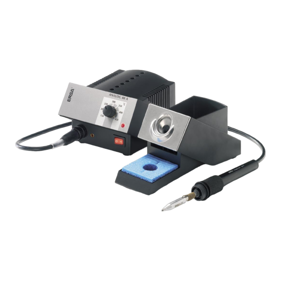
Inhalt Contents Vor Inbetriebnahme Before initial operation Inbetriebnahme Initial operation Hinweise zum Löten Soldering Arbeiten mit empfindlichen Bauelementen Working with sensitive components Lötspitzenwechsel Replacement of soldering tips Kalibrieren Calibration Fehlerdiagnose Fault diagnosis Heizkörperwechsel Basic tool 60 Replacement of heating element for Basic tool 60 Heizkörperwechsel Ergo tool Replacement of heating element for Ergo tool Heizkörperwechsel Basic tool 80... - Page 3 Abb. 1 / fig. 1 ERSA ANALOG 60 1. Versorgungseinheit 1. Power supply unit 2. Anschlussleitung 2. Lead 3. Anschlussstecker Lötkolben 3. Soldering iron plug 4. Potentialausgleichsbuchse 4. Potential equalization jack 5. Abgleichpotentiometer 5. Calibration potentiometer hole 6. Netzschalter 6. Power switch 7.
-
Page 4: Vor Inbetriebnahme
- soldering iron with soldering tip - Ablageständer mit Viskoseschwamm - holder with viscose sponge - den Sicherheitshinweisen für ERSA Wärmewerkzeuge - the safety instructions for ERSA heating tools - dieser Betriebsanleitung. - these operating instructions Sind die aufgezählten Komponenten nicht vollständig oder beschädigt, If the listed components are incomplete or damaged, please contact setzen Sie sich bitte mit Ihrem Lieferanten in Verbindung. -
Page 5: Hinweise Zum Löten
(pad) and the component join. Lötstelle erwärmen, indem die Lötspitze gleichermaßen mit Lötauge (Pad) und Bauteilanschluss in Kontakt gebracht wird. Apply solder wire (e. g. ERSA solder wire Sn95,5Ag3,8Cu0,7 as per DIN 1707 with solder core). Lötdraht zuführen (z. B. ERSA-Lötdraht Sn95,5Ag3,8Cu0,7 nach DIN 1707 mit Flussmittelseele). -
Page 6: Arbeiten Mit Empfindlichen Bauelementen
4. Arbeiten mit empfindlichen Bauelementen 4. Working with sensitive components Manche Bauelemente können durch elektrostatische Entladung Many components may be damaged by electrostatic discharge (please beschädigt werden (beachten Sie bitte die Warnhinweise auf den observe the warnings on the packaging or ask the manufacturer Verpackungen oder fragen Sie Hersteller oder Lieferant). -
Page 7: Kalibrieren
Arbeitstemperatur einstellen. required working temperature. 6.2 Mit einem Messgerät (z. B. Temperaturmessgerät 6.2 Use a measuring device (e.g. the ERSA DTM 100 ERSA DTM 100) die Temperatur an der Lötspitze temperature measuring device) to determine the ermitteln. Ist die eingestellte Temperatur stabil, temperature at the soldering bit. -
Page 8: Fehlerdiagnose
Wenden Sie sich dabei an Ihren Händler oder senden Sie das komplette Use your dealer or return the complete station to ERSA together with a Gerät mit ausführlicher Fehlerbeschreibung direkt ans Werk (Adresse detailed error description (see last page for address). -
Page 9: Heizkörperwechsel Basic Tool 60
8. Heizkörperwechsel Abb. 5 / fig. 5 8. Heating element replacement Basic tool 60 Basic tool 60 8.1 Durchgangsprüfung Heizkörper 8.1 Continuity check for heating element (Abb. 5) (fig. 5) Zwischen Messpunkt 1 und 3 sollten 6 Ohm The continuity resistance between measuring (bei kaltem Lötkolben) bis 7 Ohm (bei höherer points 1 and 3 should be between 6 Ohm Basic tool 60... -
Page 10: Heizkörperwechsel Ergo Tool
9. Heizkörperwechsel 9. Heating element replacement Abb. 7 / fig. 7 Ergo tool Ergo tool 9.1 Durchgangsprüfung Heizkörper 9.1 Continuity check for heating element (Abb. 7) (fig. 7) Zwischen Messpunkt 1 und 3 sollten 6 Ohm The continuity resistance between measuring (bei kaltem Lötkolben) Durchgangswiderstand points 1 and 3 should be 6 Ohm (at cool messbar sein. -
Page 11: Heizkörperwechsel Basic Tool 80
Abb. 10/ fig. 10 10. Heizkörperwechsel 10. Heating element replacement Basic tool 80 Basic tool 80 10.1 Durchgangsprüf. Heizkörper (Abb. 10) 10.1 Continuity check heating elem. (fig. 10) Zwischen Messpunkt 1 und 4 sollten weniger als 6 The continuity resistance between measuring points 1 Ohm (bei kaltem Lötkolben) Durchgangswiderstand and 4 should be smaller than 6 Ohm (at cool soldering messbar sein. -
Page 12: Heizkörperwechsel Power Tool
Abb. 13 / fig. 13 11. Heizkörperwechsel 11. Heating element replacement Power tool (Abb. 13) Power tool (fig. 13) 11.1 Durchgangsprüfung Heizkörper 11.1 Continuity check for heating element Zwischen Messpunkt 1 und 6 sollten weniger als 6 The continuity resistance between measuring points 1 Ohm (bei kaltem Lötkolben) Durchgangswiderstand and 6 should be smaller than 6 Ohm (at cool soldering messbar sein. -
Page 13: Technische Daten / Bestelldaten
Holder for ANALOG 60 / ANALOG 80 0A 28 Ablageständer für ANALOG 60 / ANALOG 80 0A 42 Holder antistatic for ANALOG 60 A / ANALOG 80 A 0A 29 Ablageständer antistat. für ANALOG 60 A / ANALOG 80 A 0003B... - Page 14 0832 KD 0832 PW 0832 SD* ERSA Spitzenauswahl - Bitte anfragen ! 0832 AD ERSA Tip range - Please ask for more types ! 0832 UD* 0832 OD 0832 VD * Diese Einsätze können nur im Abla- geständer A28, A29 oder A45 abgelegt werden.
- Page 15 14. Festtemperaturen 14. Fixed Temperatures Falls Festtemperaturen erwünscht sind: In case fixed temperature is required: • nach Einstellen der gewünschten Temperatur Drehknopf abziehen. • after setting the required temperature remove the knob • Schutzfolie von mitgelieferten Abdeckplättchen entfernen. • remove protection foil from enclosed cover •...
- Page 16 Genehmigung All rights reserved. This manual may not be reproduced, trans- der ERSA GmbH reproduziert, übertragen oder in eine andere mitted or in translated in another language, even in excerpt form, Sprache übersetzt werden.
- Page 17 Table des matières Содержание Комплектность поставки 1. Avant la mise en service Подготовка станции к работе 2. Mise en service Пайка 3. Remarques concernant le brasage Защита от статического электричества 4. Travaux avec des éléments de construction sensibles 5. Changement de la panne du fer à souder Замена...
- Page 18 Abb. 1 / fig. 1 ERSA ANALOG 60 1. Управляющий блок 1. Unité d’alimentation 2. Провод паяльника 2. Conduite de raccordement 3. Разъем паяльника 3. Fiche de raccordement du fer à souder 4. Разъем эквипотенциального заземления 4. Douille de compensation de potentiel 5.
-
Page 19: Avant La Mise En Service
1. Avant la mise en service Комплектность поставки Veuillez contrôler si le contenu de l’emballage est complet. Проверьте целостность содержимого упаковки. В комплект Il comprend : - unité d’alimentation поставки входят: - управляющий блок - câble de branchement au réseau - шнур... -
Page 20: Remarques Concernant Le Brasage
плате) и приложите проволочный припой (например, en fil ERSA Sn95,5Ag3,8Cu0,7 conforme à DIN 1707 avec âme à флюсосодержащий припой ERSA Sn95,5Ag3,8Cu0,7, DIN résine). 1707). Répéter l’opération de brasage. Каждый раз очищайте жало паяльника о влажную губку: пайка неочищенным жалом требует больше времени. -
Page 21: Travaux Avec Des Éléments De Construction Sensibles
Travaux avec des éléments de construction sensibles 4. Защита от статического электричества Certains éléments de construction peuvent être endommagés par une dé- Многие компоненты повреждены воздействию электростатического charge électrostatique (veuillez respecter les avis de danger sur les embal- разряда (обращайте внимание на соответствующие предупреждения lages ou renseignez-vous auprès du fabriquant ou de votre fournisseur). -
Page 22: Calibrage
6.2 Используя ваш аттестованный термометр (или 6.2 A l’aide d’un instrument de mesure (p.ex. instru- ERSA DTM100), измерьте температуру в рабочей ment de mesure de la température ERSA DTM точке паяльного жала и соотнесите показания 100), déterminer la température de la pointe à... -
Page 23: Diagnostic D'erreurs
9.2, 10.3, 11.3). Если нагревательный элемент в порядке, обратитесь к поставщику или сервисный центр ERSA для ремонта вместе с паяльником S’il y a une continuité et qu’il est impossible de localiser l’erreur, veuillez и паяльной станцией целиком. Предоставьте письмо с полным... -
Page 24: Замена Нагревателя В Паяльнике Basic Tool
8. Changement de l'élement ill. 5 / рис. 5 Замена нагревателя в thermique Basic tool 60 паяльнике Basic tool 60 8.1 Contrôle de continuité de l'élement 8.1 Проверка целостности нагревателя thermique (ill. 5) (рис. 5) Il faut pouvoir mesurer une résistance intérieure Сопротивление... -
Page 25: Замена Нагревателя В Паяльнике Ergo Tool
9. Changement de l'élément therm. 9. Замена нагревателя в паяльнике ill. 7 / рис. 7 Ergo tool Ergo tool 9.1 Contrôle de continuité de l'élément 9.1 Проверка целостности нагревателя thermique (ill. 7) (рис. 7) Il faut pouvoir mesurer une résistance intérieure Сопротивление... -
Page 26: Замена Нагревателя В Паяльнике Basic Tool
ill. 10 / рис. 10 10. Changement de l'élément therm. 10. Замена нагревателя в паяльнике Basic tool 80 (ill. 10) Basic tool 80 (рис. 10) 10.1 Contrôle de continuité de l'élém. therm. 10.1 Проверка целостности нагревателя Il faut pouvoir mesurer une résistance intérieure de 6 Ohm Сопротивление... -
Page 27: Замена Нагревателя В Паяльнике Power Tool
ill. 13 / рис. 13 11. Changement de l'élément therm. 11. Замена нагревателя в Power tool (ill. 13) паяльнике Power tool (рис.13) 11.1 Contrôle de continuité de l'élém.therm. 11.1 Проверка целостности нагревателя Il faut pouvoir mesurer une résistance intérieure de 6 Ohm Сопротивление... -
Page 28: Технические Данные И Номенклатурные Номера
Elément thermique pour Power tool 084100J 084100J Нагреватель для Power tool 0A 41 0A 41 Support de réception pour ANALOG 60 / ANALOG 80 Держатель к ANALOG 60 / ANALOG 80 Support de réception antistatique 0A 42 0A 42 Держатель антистатический... - Page 29 0832 MD 0832 KD ERSA pannes SolderWell Жала ERSA SolderWell 0832 SD* 0832 PW ERSA pannes: Autres types sur demande! Запросите весь перечень жал ERSA! 832 UD* 0832 AD 0832 VD 0832 OD Attention : seuls les supports de fer A28, A29 ou A45 sont adaptés pour accueillir ces pannes à...
-
Page 30: Фиксация Температуры
14. Température fixe Фиксация температуры Si l'on souhaite verouiller l'appareil sur une température fixe Выверенную температуру пайки можно зафиксировать: • выньте ручку регулятора из передней панели корпуса станции • Après avoir règlée la température souhaitée, enlever le bouton • удалите защитную фольгу с вкладки, входящей в комплект •... - Page 31 Garantie Гарантии ERSA a pris grand soin lors de la composition de ce mode Гарантия ERSA не распространяется на элементы, d‘emploi. Cependant, nous n‘offrons aucune garantie concernant подверженные износу (паяльные жала, насадки для le contenu, la complétude ou la qualité des informations выпааивания, нагреватели), а...
- Page 32 Indice Contenido 1. Prima della messa in funzione 1. Antes de la puesta en marcha 2. Messa in funzione 2. Puesta en marcha 3. Indicazioni sulla saldatura 3. Instrucciones para la soldadura 4. Lavori con componenti sensibili 4. Trabajos con elementos constructivos sensibles 5.
- Page 33 fig. 1 / fig. 1 ERSA ANALOG 60 1. Alimentatore 1. Fuente de alimentación 2. Linea di allacciamento 2. Cable de conexión 3. Spina saldatoio 3. Conector del soldador 4. Jack di compensazione potenziale 4. Toma de compensación del potencial 5.
-
Page 34: Prima Della Messa In Funzione
1. Prima della messa in funzione 1. Antes de la puesta en marcha Si prega di controllare che il contenuto della confezione sia completo. Por favor, compruebe el contenido del embalaje para verificar que está Esso è composto da: completo. En su interior debe hallar: - alimentatore - La fuente de alimentación - cavo di rete... - Page 35 (pad) y la conexión de la pieza. Alimentare filo di saldatura (ad es. filo di saldatura ERSA Sn95,5Ag3,8Cu0,7 secondo il DIN 1707 con anima di fon- Suministrar alambre de soldadura (por ejemplo, alambre de solda- dente).
-
Page 36: Lavori Con Componenti Sensibili
4. Lavorare con componenti sensibili 4. Trabajos con elementos constructivos sensibles Alcuni componenti possono venire danneggiati dalla scarica elettrosta- Algunos elementos constructivos pueden resultar dañados por las des- tica (si prega di fare attenzione alle avvertenze riportate sulla confezione cargas electrostáticas (lea las indicaciones de advertencia de los emba- oppure di chiedere consiglio alla ditta o al fornitore). -
Page 37: Calibrare
6.2 Con un apparecchio di misura (ad es. apparecchio 6.2 Con un instrumento de medición (p.ej. medidor de per la misurazione della temperatura ERSA DTM temperatura ERSA DTM 100) determinar la tempe- 100) accertare la temperatura della punta di salda- ratura en la punta del soldador. -
Page 38: Diagnosi Dei Guasti
7. Diagnosi guasti 7. Diagnóstico de averías Se la stazione di saldatura non dovesse funzionare in modo adeguato, Si la estación de soldadura no funciona según lo esperado, efectúe las va controllata nel modo seguente: comprobaciones siguientes. • C'è corrente (il cavo di alimentazione è correttamente all'attacco della •... -
Page 39: Sostituzione Dell'elemento Riscaldante Basic Tool
Sostituzione dell'elemento fig. 5 Cambio del calefactor riscaldante Basic tool 60 Basic tool 60 8.1 Controllo del passaggio dell'elemento Comprobación del paso de energía riscaldante (fig. 5) en el calefactor (fig. 5) La resistenza di continuità tra i punti di misurazione Entre el punto de medición 1 y el 3 deberían 1 e 3 deve essere tra i 6 Ohm (a saldatore freddo) e i poderse medir 6 ohmios (en caso de soldador frío) -
Page 40: Cambio Del Calefactor Ergo Tool
Sostituzione dell'elemento 9. Cambio del calefactor fig. 7 riscaldante Ergo tool Ergo tool 9.1 Controllo del passaggio 9.1 Comprobación del paso de energía dell'elemento riscaldante (fig. 7) en el calefactor La resistenza di continuità tra i punti di misura- Entre el punto de medición 1 y el 3 deberían zione 1 e 3 deve essere tra i 6 Ohm (a salda- poderse medir 6 ohmios (en caso de soldador tore freddo). -
Page 41: Cambio Del Calefactor Basic Tool
10. Sostituzione dell'elemento fig. 10 10. Cambio del calefactor riscaldante Basic tool 80 Basic tool 80 10.1 Controllo dell passaggio 10.1 Comprobación del paso de energía en el dell'elemento riscaldante (fig. 10) calefactor (fig. 10) La resistenza di continuità tra i punti di misurazione 1 e 4 Entre el punto de medición 1 y el 4 deberían poderse medir deve essere meno di 6 Ohm (a saldatore freddo). -
Page 42: Cambio Del Calefactor Power Tool
fig. 13 11. Sostituzione dell'elemento 11. Cambio del calefactor riscaldante Power tool (fig. 13) Power tool (fig. 13) 11.1 Controllo dell pass. dell'elem. riscald. 11.1 Comprobación del paso de energía en el calefactor La resistenza di continuità tra i punti di misurazione 1 e 6 deve essere meno di 6 Ohm (a saldatore freddo). -
Page 43: Datos Técnicos / Datos De Pedidos
Estatión de soldadura completa ANALOG 60 / 60 W 0ANA 60 ANALOG 60 / 60 W 0ANA 60 ANALOG 60 A / 60 W antistatica 0ANA 60 A ANALOG 60 A / 60 W antistática 0ANA 60 A ANALOG 80 / 80 W... - Page 44 Inserti dissaldanti 0832 CD Suplementos para desoldar 0832 LD a richiesta 0832 ED a petición* ERSA Punte SolderWell 0832 MD ERSA Puntas SolderWell 0832 KD 0832 PW 0832 0SD* Altre punte a richiesta! ¡Gama de las puntas – pida por favor más tipos!
- Page 45 Garantía Garanzia ERSA ha realizzato queste istruzioni per l‘uso con molta cura; tut- ERSA ha elaborado esmeradamente estas instrucciones tavia non può assumersi la responsabilità in merito al contenuto, de funcionamiento. Sin embargo, no podemos asumir alla completezza e alla qualità delle indicazioni qui riportate. Il responsabilidad alguna con respecto al contenido, exhaustividad contenuto viene curato e adattato alle circostanze attuali.
- Page 46 Notizen / Notes...
- Page 47 Notizen / Notes...
- Page 48 © 06/2005, ERSA GmbH • 3BA00026-01 ERSA GmbH • Leonhard-Karl-Str. 24 • 97877 Wertheim / Germany Tel. +49 (0) 9342/800-0 • Fax -100 • e-mail: info@ersa.de • www.ersa.com...
Need help?
Do you have a question about the ANALOG 60 and is the answer not in the manual?
Questions and answers