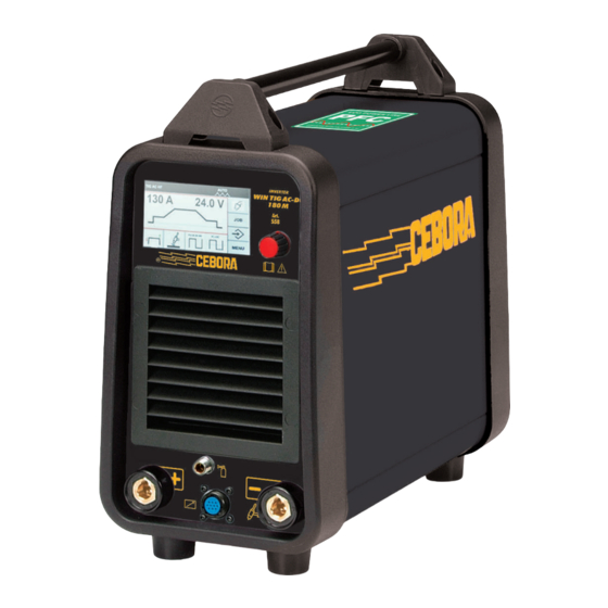
Cebora WIN TIG AC-DC 180 M Instruction Manual
Arc welding machine
Hide thumbs
Also See for WIN TIG AC-DC 180 M:
- Instruction manual (124 pages) ,
- Instruction manual (164 pages) ,
- Instruction manual (172 pages)
Advertisement
Available languages
Available languages
Quick Links
IT
-MANUALE DI ISTRUZIONI PER SALDATRICE AD ARCO
EN
-INSTRUCTION MANUAL FOR ARC WELDING MACHINE
NL
-GEBRUIKSAANWIJZING VOOR BOOGLASMACHINE
Schémas électriques et liste des pièces de rechange / Cf. Annexe
Esquemas elétricos e lista de peças sobresselentes / Veja Anexo
Elektrische Schema's En Lijst Van Reserveonderdelen / Zie bijlage
ΗΛΕΚΤΡΙΚΑ ΔΙΑΓΡΑΜΜΑΤΑ & ΚΑΤΑΛΟΓΟΣ ΑΝΤΑΛΛΑΚΤΙΚΩΝ /Βλέπε ΠΑΡΑΡΤΗΜΑ
3301027/A
Parti di ricambio e schemi elettrici / vedi Allegato
Spare parts and wiring diagrams / see Annex
Schaltpläne und Ersatzteilliste / Siehe Anlage
Esquemas eléctricos & lista recambios / Ver Anexo
Sähkökaaviot & varaosaluettelo / Ks.Liite
El-diagrammer & liste over reservedele / Se Bilag
Elscheman och reservdelslista / Se Bilaga
pag. 2
page 20
pag.37
1
19/12/2019
Advertisement

Related Manuals for Cebora WIN TIG AC-DC 180 M


Summary of Contents for Cebora WIN TIG AC-DC 180 M
- Page 1 -MANUALE DI ISTRUZIONI PER SALDATRICE AD ARCO pag. 2 -INSTRUCTION MANUAL FOR ARC WELDING MACHINE page 20 -GEBRUIKSAANWIJZING VOOR BOOGLASMACHINE pag.37 Parti di ricambio e schemi elettrici / vedi Allegato Spare parts and wiring diagrams / see Annex Schaltpläne und Ersatzteilliste / Siehe Anlage Schémas électriques et liste des pièces de rechange / Cf.
- Page 2 MANUALE DI ISTRUZIONI PER SALDATRICI AD ARCO COMPATIBILITÀ ELETTROMAGNETICA IMPORTANTE: PRIMA DELLA MESSA IN OPERA DEL- Questo apparecchio è costruito in conformità alle indicazioni L’APPARECCHIO LEGGERE IL CONTENUTO DI QUESTO contenute nella norma IEC 60974-10(Cl. A) e deve essere MANUALE E CONSERVARLO, PER TUTTA LA VITA OPE- usato solo a scopo professionale in un ambiente indu- RATIVA, IN UN LUOGO NOTO AGLI INTERESSATI.
- Page 3 1.2 Isolarsi dal pezzo da saldare e dal suolo. 2 DESCRIZIONI GENERALI 1.3 Scollegare la spina del cavo di alimentazione prima di lavorare sulla macchina. 2.2 SPECIFICHE 2. Inalare le esalazioni prodotte dalla saldatura può es- sere nocivo alla salute. Questa saldatrice è...
- Page 4 IEC 60974-1 ® WIN TIG AC DC 180 M Via A.Costa, 24 - 40057-Cadriano-Bologna-Italy IEC 60974- INVERTER Art. IEC 60974-10 (Cl. A) WIN TIG AC-DC 5 /10 -180 /17,2 180 M Art. 17,2 14,4 1x230 -50/60 1max= 1eff= 10 /20 -130 /25,2 25,2 23,6 1x230 -50/60...
- Page 5 F – CONNETTORE 10 POLI IMPORTANTE da ora in poi questa procedura sarà A questo connettore vanno collegati i seguenti comandi re- descritta indicando : moti: selezionare e confermare a) pedale confermando questo simbolo si tor- b) torcia con pulsante di start nerà...
- Page 6 parametri di saldatura riassunti in tabella 1. 4.1.2 IMPOSTAZIONE DELL’ACCENSIONE DELL’AR- Come esempio è descritta la procedeura per la regola- CO (PARAGRAFO 6) zione del tempo di Pre-Gas. Selezionare Selezionare e conferma- il parametro re il tipo di desiderato. ll accensione.
- Page 7 Descrizione Min. U.M. Ris. Diametro elettrodo 0.5 / 1.6/ 4.0 / 0.1/ (solo per processi di saldatura TIG 0,0197 0,0630 0,1575 inch 0,039 inch inch inch Tempo pre gas 0,05 0,01 Tempo prima corrente Sec. Ampiezza prima corrente point Tempo salita corrente Sec.
- Page 8 Saldatura MMA con elettrodo rivestito (vedi capi- 6 SCELTA DEL TIPO DI ACCENSIONE DELL’ARCO tolo 13) (SETTORE P) Selezionare Saldatura TIG DC (vedi capitolo 17) e conferma- re il settore relativo Saldatura TIG DC APC (Activ Power Control, vedi all'accensio- capitolo 16) ne dell'arco.
- Page 9 7.2 MODO AUTOMATICO: Toccare il pezzo da lavorare con la punta dell’e- lettrodo, premere il pulsante torcia e solleva- re la punta dell’elettrodo. Appena l’elettrodo si adatto a realizzare saldature di lunga durata. solleva si genera una scarica di alta frequenza/ tensione che accende l’arco, inoltree sono impostati dei parametri che favoriscono l’unione dei lembi del materia- le nella prima fase di saldatura.
- Page 10 8 PULSAZIONE (SETTORE N) 7.5 PUNTATURA MANUALE (2T): Selezionare La saldatrice si predispone automaticamente per confer- l’accensione con alta frequenza (paragrafo 6) mare il set- tore N re- Il tempo di lativo alla p u n t a t u r a p u l s a zi o n e si attiva in per accede-...
- Page 11 Parametro Min. U.M. Ris. 9 MENU (SETTORE M) POINT Selezionare e conferma- re il settore Corrente MENU di base 0,16 0,16 0,01 ÷ Frequenza Selezionare e conferma- re il tipo di argomento. Duty Cicle 8.2 PULSE ON-XP Selezionando l'icona PULSE ON-XP si imposta una cor- rente pulsata ad altissima frequenza per ottenere un arco 9.1 INFORMAZIONI (INFORMATION) più...
- Page 12 TABELLA REGOLAZIONE PARAMETRI PROCESSI AC Processo Descrizione Min. U.M. Ris. BILANCIAMENTO AC EP 8 EP-8 EN-8 EN 8 TIG AC FREQUENZA AC BILANCIAMENTO AC EP 8 EP-8 EN-8 EN 8 FREQUENZA AC AC + DC DUTY CYCLE BILANCIAMENTO AC EP 8 EP-8 EN-8 EN 8...
- Page 13 TUTTO (ALL) = Riporta la saldatrice alle impostazioni di cifra successiva. Nello stesso modo impostare le altre fabbrica comprese le memorie (JOBS). cifre. JOBS ESCLUSI (EXCLUDING JOBS )= Riporta la sal- Sono disponibili le impostazioni tecniche elencate nella figure successive datrice alle impostazioni di fabbrica escludendo le me- morie.
- Page 14 Ruotare manopola B impo- stare il para- metro scelto quindi pre- mere confermare l ’ i m p o s t a - zione. LEGENDA SIMBOLI Con questo metodo si possono selezionare, modificare e confermare tutti i parametri di saldatura che si presen- memorizzare tano in successione e che sono riassunti nella seguente tabella.
- Page 15 10.2 MODIFICARE UN JOB Per modificare o utilizzare un programma procedere Scegliere come segue: numero memoria in • Entrare nel menù “JOB” come descritto in 10.1 cui si vuole • Selezionare il “JOB” da modificare inserire • Selezionare e confermare il settore "richiamare" JOB copiato Per tornare alla schermata principale premere la mano- pola B per un tempo lungo (>...
- Page 16 Per tornare alla schermata principale premere la mano- 10.5 SALDARE CON UN JOB pola B per un tempo lungo (> 0,7 sec.) Entrare nel menù JOB come descritto in 10.1 11 (SETTORE S) Selezionare Questo settore, posizionato nella parte alta del display, e conferma- riassume brevemente le impostazioni di saldatura e il re il numero...
- Page 17 15. TIG DC APC (ACTIV POWER CONTROL) Selezionare Questa funzione agisce in modo che quando si riduce la e conferma- lunghezza d’arco avvenga un aumento di corrente e vice- re il settore versa; quindi l’operatore controlla l’apporto termico e la relativo penetrazione con il solo movimento della torcia.
- Page 18 • Collegare il raccordo del tubo gas della torcia al rac- 18 CODICI ERRORE cordo E della macchina ed il tubo gas proveniente dal riduttore di pressione della bombola al raccordo gas H. • Accendere la macchina. Err. Descrizione Rimedio •...
- Page 19 Err. Descrizione Rimedio Tensione secondaria Spegnere e riac- Err. pericolosa cendere la sal- 40-2 datrice. Se il pro- blema persiste contattare il cen- Err. 40 tro di assistenza. N.B = La spia < 48 V AC è spen- In queste condi- zioni è...
- Page 20 INSTRUCTION MANUAL FOR ARC WELDING MACHINE structions contained in the standard IEC 60974-10 (CL. A), IMPORTANT: BEFORE STARTING THE EQUIPMENT, and must be used solely for professional purposes in READ THE CONTENTS OF THIS MANUAL, WHICH an industrial environment. There may be potential dif- MUST BE STORED IN A PLACE FAMILIAR TO ALL US- ficulties in ensuring electromagnetic compatibility in ERS FOR THE ENTIRE OPERATIVE LIFE-SPAN OF THE...
- Page 21 2.1 Keep your head out of fumes. EXPLANATION OF THE TECHNICAL SPECIFI- 2.2 Use forced ventilation or local exhaust to remove CATIONS LISTED ON THE MACHINE PLATE. fumes. This machine is manufactured according to the following international standards: IEC 60974.1 - IEC 60974.3 -IEC 60974.10 CL.
- Page 22 IEC 60974-1 ® WIN TIG AC DC 180 M Via A.Costa, 24 - 40057-Cadriano-Bologna-Italy IEC 60974- INVERTER Art. IEC 60974-10 (Cl. A) WIN TIG AC-DC 5 /10 -180 /17,2 180 M Art. 17,2 14,4 1x230 -50/60 1max= 1eff= 10 /20 -130 /25,2 25,2 23,6 1x230 -50/60...
- Page 23 a) pedal b) welding torch with start button on selecting and confirming this c) welding torch with potentiometer (5 kΩ) symbol, factory parameters d) welding torch with up/down etc… shall be set G – SWITCH To return to the main screen from IMPORTANT Starts and stops the machine any condition, press and hold knob...
- Page 24 4.1.3 SET START-UP MODE (PARAGRAPH 7 Confirm and set the se- Select and confirm the lected r a m e t e r . s t a r t - u p Then press mode. confirm next setting choice auto- a u t o m a t - m a t i c a l l y ically...
- Page 25 Description Min. U.M. Ris. Electrode diameter 0.5 / 1.6/ 4.0 / 0.1/ (only for TIG AC welding proces- 0,0197 0,0630 0,1575 inch 0,039 ses) inch inch inch Pre-Gas time 0,05 0,01 S.C. Time Sec. Amplitude of first current point Current ramp up time Sec.
- Page 26 The processes available are as follows: Select confirm type MMA Welding with covered electrodes (see of ignition. chapter 13)) N.B. the box for the pro- cess in use TIG DC WELDING (see chapter 17) is highlight- ed in green. By adopting TIG DC APC WELDING (Active Power Control, this method, See chapter 16)o 16)
- Page 27 7.3 THREE-LEVELS MODE: 7 CHOICE OF START-UP MODE (SECTOR O) Times of the currents are controlled manually; Select confirm sec- currents are restored. tor O relative start-up modes. 7.4 FOUR-LEVELS MODE: Select With this mode, the operator can introduce an inter- confirm the mediate current and restore it during welding.
- Page 28 Set and con- firm the spot The parame- w e l d i n g ter activates time, then in red. press with- out releasing immediately to return to initial w e l d i n g screen, and adjust the current. Confirm and set the selected parameter.
- Page 29 Select the desired parameter. The parameter activates in red. Confirm and set the selected parameter. Then press to confirm the setting and automatically move on to the next parameter, or turn knob B to select the desired pa- rameter. 9 MENU (SECTOR M) Select and c o n f i r m To return to the main screen, press knob B (do not re-...
- Page 30 9.3 FACTORY SETUP Select confirm the Select and type of top- confirm the type of set- ting 9.1 INFORMATION (ALL) = Restore the welding machine to factory settings, All the information that must be provided to the technical including memories (JOBS). personnel for welding machine repair and upgrading (see EXCLUDING JOBS = Restore the welding machine to initial screen) is displayed.
- Page 31 By adopting this method, it is possible to select, modi- 9.4 TECHNICAL SETTING fy and confirm all the welding parameters which present one after the other, and summarised in the following ta- To prevent inadvertent access to this menu, a password ble.
- Page 32 LEGEND OF SYMBOLS 10.2 MODIFY A JOB save restore delete copy To modify or use a program, proceed as follows: • Access the JOB menu as described in 10.1 10.1 SAVE A WELDING SPOT. (JOB)) • Select the JOB to be modified •...
- Page 33 10.5 WELDING WITH A JOB Access the JOB menu as described in 10.1 Select c o n f i r m the desired number. Select m e m o r y number Select and confirm the which JOB sector. copied JOB is to be in- sertede JOB copiato...
- Page 34 Confirmation enables access to the following welding 11 (SECTOR S) parameters: • HOT-START CURRENT adjustable from 0 to 100% of This sector is positioned on the upper part of the display. the welding current (with saturation at maximum current). It provides in summary form the welding settings, and Percentage of current added to the welding current partial or total block of parameters.
- Page 35 • If gas-lens type accessories are used, the gas delivery ues, contact the must be reduced by approximately 3 times the electrode Err. 01 CEBORA assis- diameter. tance service.. • The ceramic nozzle diameter must be between 4 and 6...
- Page 36 40-2 turn it back on. If the problem con- tinues, contact Err. 40 the CEBORA as- sistance service. NOTE = With this error the < 48 V AC light is off. In these condi- tions, the machi-...
- Page 37 MANUALE DI ISTRUZIONI PER SALDATRICI AD ARCO explosief stof, gassen of dampen. · Alle cilinders en druk- IBELANGRIJK: LEES VOORDAT U MET DEZE MACHI- regelaars die bij laswerkzaamheden worden gebruik die- NE BEGINT TE WERKEN DE GEBRUIKSAANWIJZING nen met zorg te worden behandeld. AAN-DACHTIG DOOR EN BEWAAR ZE GEDURENDE DE VOL-LEDIGE LEVENSDUUR VAN DE MACHINE OP EEN COMPATIBILITÀ...
- Page 38 1.1 PLAATJE MET WAARSCHUWINGEN 3.2 De vonken die door het lassen veroorzaakt worden, kunnen brand veroorzaken. Houd een blusapparaat binnen handbereik en zorg ervoor dat iemand altijd gereed is om het te gebruiken. 3.3 Voer nooit lassen uit op gesloten houders. De stralen van de boog kunnen uw ogen en huid verbranden.
- Page 39 IEC 60974-1 ® WIN TIG AC DC 180 M Via A.Costa, 24 - 40057-Cadriano-Bologna-Italy IEC 60974- INVERTER Art. IEC 60974-10 (Cl. A) WIN TIG AC-DC 5 /10 -180 /17,2 180 M Art. 17,2 14,4 1x230 -50/60 1max= 1eff= 10 /20 -130 /25,2 25,2 23,6 1x230 -50/60...
- Page 40 C - POSITIEVE AANSLUITKLEM (+) instellingen van de gekozen sector te openen. • De laatste instelling wordt groen en in een rood D – NEGATIEVE AANSLUITKLEM (-) kader weergegeven. Het rode kader verplaatst zich naar de nieuwe keuze wanneer de nieuwe selectie is E –...
- Page 41 Als voorbeeld beschrijven we de procedure voor het in- 4.1.2 INSTELLING VAN DE ONTSTEKING VAN DE stellen van de Pre Gas-tijd BOOG (PARAGRAAF 6) Selecteer en Selecteer de bevestig het g e w e n s t e type ontste- p a r a m e te r.
- Page 42 Beschrijving Min. M.E. Res. Diameter elektrode 0.5 / 1.6/ 4.0 / 0.1/ (uitsluitend voor TIG AC-laspro- 0,0197 0,0630 0,1575 inch 0,039 cessen) inch inch inch Pre Gas-tijd 0,05 0,01 Tijd eerste stroom Sec. Amplitude eerste stroom point Tijd stroomtoename Sec. Lasstroom Tijd stroomafname Sec.
- Page 43 MMA lassen met beklede elektrode (zie ho- Selecteer en ofdstuk 13 bevestig het type ontste- king. TIG DC lassen (zie hoofdstuk 17) N.B. hokje de gebruikte o n t s t e k i n g TIG DC APC lassen (Activ Power Control, zie ho- wordt groen ofdstuk 16) w e e r g e g e -...
- Page 44 7 KEUZE VAN DE STARTWIJZE (SECTOR O) Kies en be- vestig sector b e h o r e n - startwijzen 7.3 DRIE NIVEAUS: De stroomtijden worden met de hand ingesteld en roepen de stromen op. Kies en be- vestig startwijze.
- Page 45 8 PULSAZIONE (SETTORE N) 7.5 HANDBEDIEND PUNTLASSEN (2T): Selecteer en Het lasapparaat bereidt zich automatisch voor op de bevestig de ontsteking met hoge frequentie (paragraaf 6) sector N voor het pulslassen om de wijze puntlastijd PULSE ON wordt rood (hfdst. 8.1) of eergegeven.
- Page 46 Parameter Min. U.M. Ris. 9 MENU (SETTORE M) 0,16 0,16 0,01 ÷ S e l e c t e e r en bevestig sector Frequentie MENU Duty Cicle Selecteer en 8.2 PULSE ON-XP bevestig de g e w e n s t e Selecteer de icoon PULSE ON-XP om een pulsstroom taal met zeer hoge frequentie voor een geconcentreerdere...
- Page 47 TABELLA REGOLAZIONE PARAMETRI PROCESSI AC Processo Descrizione Min. U.M. Ris. BILANCIAMENTO AC EP 8 EP-8 EN-8 EN 8 TIG AC FREQUENZA AC BILANCIAMENTO AC EP 8 EP-8 EN-8 EN 8 FREQUENZA AC AC + DC DUTY CYCLE BILANCIAMENTO AC EP 8 EP-8 EN-8 EN 8...
- Page 48 ALLE (ALL) = Herstelt de fabrieksinstellingen van het gende afbeeldingen genomen worden, zijn beschikbaar. lasapparaat in, m.i.v. de geheugens (JOBS). Stel op dezelfde manier de andere cijfers in. JOBS UITGESLOTEN (EXCLUDING JOBS) = Herstelt De technische instellingen die in de volgende afbeeldingen de fabrieksinstellingen van het lasapparaat in, m.u.v.
- Page 49 Stel de geko- zen parame- ter in door aan de knop B te draaien druk op de knop om de instelling bevestigen. deze manier kunnen alle lasparameters LEGENDA SYMBOLEN achtereenvolgens weergegeven worden en in de volgende tabel genoemd zijn worden geselecteerd, gewijzigd en opslaan bevestigd.
- Page 50 Verricht de volgende procedure: • Open het menu JOB zoals is beschreven in 10.1 Sla het pro- • Selecteer de te kopiëren JOB en selecteer de sector g r a m m a kopiëren. in het ge- heugen op door de icoon slaan te kie- zen en be-...
- Page 51 Selecteer en bevestig de sector EXIT Per tornare alla schermata principale premere la mano- 10.5 LASSEN MET EEN JOB pola B per un tempo lungo (> 0,7 sec.) Open het menu JOB zoals is beschreven in 10.1 11 (SECTOR S) Deze sector, bovenaan in het display, bevat een beknopte S e l e c t e e r opsomming van de lasinstellingen en de gedeeltelijke of...
- Page 52 lasap- paraat Stel de duur onmiddellijk lasstro- vestig om regelen keuze door aan de knop B te draaien. Verricht de volgende procedure als u de lasparameters wilt wijzigen: 15. TIG DC APC (ACTIV POWER CONTROL) Selecteer en Deze functie reageert op dusdanige wijze dat de stroom bevestig de verhoogt wordt wanneer de booglengte afneemt, en sector beho-...
- Page 53 16. TIG DC - TIG AC - TIG AC+DC - TIG AC XP 17 BEDIENINGEN OP AFSTAND EN ACCESSOIRES LASSEN Voor het instellen van de lasstroom kunnen de volgende bedieningen op afstand op dit lasapparaat worden aan- Dit lasapparaat kan worden gebruikt voor het TIG-lassen gesloten: van roestvrij staal, ijzer en koper en van aluminium, ma- Art.1260 TIG-lastoorts met één knop (luchtgekoeld).
- Page 54 de schakelaar G op "O" is geplaatst en of de voedingskabel Err. Beschrijving Oplossing niet langer is aangesloten op het elektriciteitsnet. Kwaliteitscontrole Controleer Err. Verwijder metaalstof regelmatig uit de binnenkant van (hoge spanning de ingestelde 84-2 het apparaat. Maak daarvoor gebruik van perslucht. tijdens lassen) tiveringsspanning door MENU te...
- Page 56 CEBORA S.p.A - Via Andrea Costa, 24 - 40057 Cadriano di Granarolo - BOLOGNA - Italy Tel. +39.051.765.000 - Fax. +39.051.765.222 www.cebora.it - e-mail: cebora@cebora.it...
Need help?
Do you have a question about the WIN TIG AC-DC 180 M and is the answer not in the manual?
Questions and answers