
Related Manuals for Motorola NNTN9212


Summary of Contents for Motorola NNTN9212
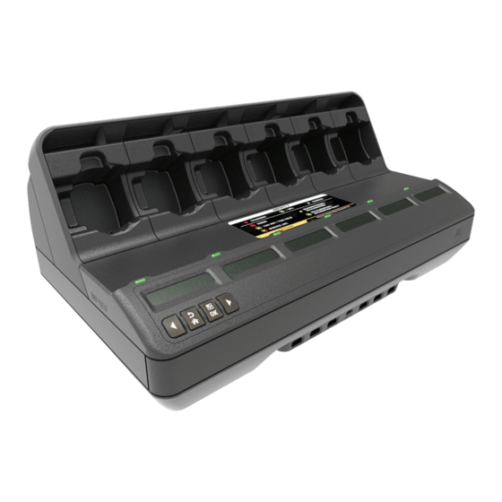
- Page 1 APX-SERIES IMPRES™ 2 MULTI-UNIT CHARGER POCKET INSERT KITS NNTN9212 SERVICE MANUAL REPLACING POCKET INSERTS en-US...
-
Page 3: Getting Started
Charger Model Charger Description Pocket Insert Kit 6-Display IMPRES 2 MUC with Charger PS000337A01 Reprogramming, IMPRES NNTN9212 (UNIV) 2 Fleet Management, and USB Accessory Charging Only (APX NEXT) REQUIRED TOOLS • Torque Screwdriver set for 6 in-lbs • Torx T10 Screwdriver bit... - Page 4 PREREQUISITES • Use a clean place to perform the procedure. Ensure no debris or liquid enters into the charger. • Use Electrostatic Discharge (ESD) Best Practices: - Work on a hard surface such as table, counter top, or plank of wood. - Stand on a hard floor such as wood, or tile.
- Page 5 3. Hold the rear shroud along the sides, and pull it away from the unit to detach it. Figure 2: Shroud removal. 4. Remove the TorxT10 screws on each pocket insert being replaced. Figure 3: Pocket insert screw removal.
- Page 6 5. Slightly lift the back of the pocket insert to disengage the pocket insert from the post. Then, push the pocket insert out towards the front of the unit to remove the pocket insert. Figure 4: Pocket insert removal.
- Page 7 6. Unplug the cable for the pocket insert from the unit, and note the orientation of the receptacle. Figure 5: Cable removal for each pocket insert. Figure 6: The connector is keyed and only fits one way into the charger.
- Page 8 7. Plug in the cable to install the new pocket insert. The connector is keyed to ensure proper orientation. The procedure results in a half twist of the harness. NOTE: If the connector disengages from the main board after pocket insert installation, reinstall the connector before securing the pocket insert screw.
- Page 9 Figure 8: Slightly tug on the cable to ensure it is correctly positioned and tightened in the receptacle.
- Page 10 8. Align the pocket back into the charger, and slide it back until the pocket snaps into place. Figure 9: Rotate the pocket around and align it to the charger. The wires are half twisted. Do not pull up on the wire harness. Figure 10: The screw hole of the pocket will align to the hole in the charger.
- Page 11 Figure 11: Reinstall the T10 screw and tighten to 6 in-lbs. 9. Slide the rear shroud onto the unit. Slide both sides forward, and lock the tabs into place to reinstall the hood. Figure 12: Hood reinstallation.
- Page 12 Figure 13: Shroud screws installation. 10. Reinstall the four #2 Phillips screws to secure the shroud. 11. Plug in the AC Power cord into the MUC. Ensure all six pocket LED illuminate in GREEN color for one second.
- Page 14 NOTES...
- Page 16 11900 Bayan Lepas, Penang. Malaysia. MOTOROLA, MOTO, MOTOROLA SOLUTIONS and the Stylized M logo are trademarks or registered trademarks of Motorola Trademark Holdings, LLC and are used under license. All other trademarks are the property of their respective owners. © 2019 Motorola Solutions, Inc. All rights reserved.
Need help?
Do you have a question about the NNTN9212 and is the answer not in the manual?
Questions and answers