Monogram ZV800 Installation Instructions Manual
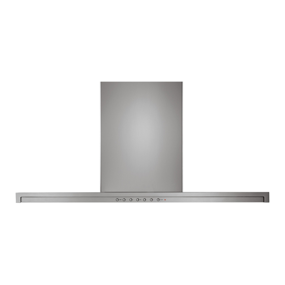
30” chimney vent hood
Hide thumbs
Also See for ZV800:
- Installation instructions manual (48 pages) ,
- Owner's manual (24 pages) ,
- Installation instructions manual (48 pages)
Advertisement
Quick Links
Advertisement

Related Manuals for Monogram ZV800


Summary of Contents for Monogram ZV800
- Page 1 INSTALLATION INSTRUCTIONS 30” Chimney Vent Hood ZV800 MONOGRAM.COM...
- Page 2 Skill Level — Installation of this appliance requires AVERTISSEMENT basic mechanical and electrical skills. Completion Time — 1 to 3 Hours. is not covered under the warranty. monogram.com. accidentelle. S’il n’est pas possible de verrouiller le monogram.ca monogram.com/use-and-care/parts. CAUTION wiring must be done by qualified person(s). In...
- Page 3 Design Information CONTENTS Safety Information ............2 Wall-Mounted Installation—Recirculating ......... 14 Design Information ....14 ......3 ......... 15 Installation Options ............3 ........... 15 ......4 ..........16 ..............4 ......... 16 ..............5 ........... Installation Preparation .......... Tools and Materials Required ........6 ............
- Page 4 Wall Framing for Adequate Support outdoors. must be provided in all types of installations. The hood air system in accordance with local building code requirements. Visit Monogram.com for available makeup air solutions. CAUTION To reduce risk of fire and to properly on site before final framing and wall finishing.
- Page 5 6” Round roof vent 26 ft local building code requirements. Visit Monogram.com for available makeup air solutions. length of duct pieces are based on actual tests conducted by Total Duct Run good venting performance with any ventilation hood.
- Page 6 Installation Preparation TOOLS AND MATERIALS REQUIRED (NOT SUPPLIED) Spirit level Measuring tape Knife Electric drill with 1/8” and 3/8” Bits Safety glasses Duct tape edges Hammer branch circuit Strain relief for head screwdriver Conduit installation Saw or jig saw Masking tape and conduit connector REMOVE THE PACKAGING 2-piece duct...
- Page 7 Installation Preparation WALL MOUNT INSTALLATIONS Wall Mount ZV830 Installation Heights These hoods may be installed onto a wall or below a wall cabinet. *Possible Actual Ceiling *Possible VENTED RECIRCULATING Height Installation Height Installation Height 24” to 28” 24” to 25” 8’-1”...
- Page 8 Installation Preparation CHECK INSTALLATION HARDWARE 4 wood screws 4 wall fasteners Duct bracket recirculating installations only 12" Mounting bracket 1 charcoal filter for recirculating installations screws to secure 29-7/8" 27-3/4" top of motor compartment 11-1/2" 2 stainless steel filters 2-piece decorative duct cover (dimension shown for reference only) screws to secure duct cover...
- Page 9 Installation Instructions WALL-MOUNTED INSTALLATION—VENTED TO THE OUTSIDE DUCTWORK, WIRING LOCATIONS INSTALL FRAMING FOR HOOD SUPPORT IMPORTANT: Framing must be capable of supporting 100 lbs. 6” min. opening for ductwork 8" Min. Opening for Ductwork - Use a level to draw a straight pencil line on the wall. 3-3/4”...
- Page 10 Installation Instructions WALL-MOUNTED INSTALLATION—VENTED TO THE OUTSIDE INSTALL MOUNTING BRACKET INSTALL DUCT BRACKET The duct bracket must be intalled against the ceiling. This vent hood must be secured to the horizontal This bracket will hold the duct cover in place at the support or wall studs.
- Page 11 Installation Instructions WALL-MOUNTED INSTALLATION—VENTED TO THE OUTSIDE MOUNT THE HOOD PREPARE THE HOOD Install a wood Mounting screw on each bracket and tape. side of the mounting frame Remove 2 side cover screws Electrical panel wall on each side of the mounting bracket. the electrical panel.
- Page 12 Installation Instructions WALL-MOUNTED INSTALLATION—VENTED TO THE OUTSIDE CONNECT DUCTWORK CONNECT ELECTRICAL Verify that power is turned off at the source. airflow as illustrated. WARNING If house wiring is not 2-wire with seal. aluminum-to-copper connectors. AVERTISSEMENT Si la maison n’est pas câblee avec d’utiliser des connecteurs aluminium à...
- Page 13 Installation Instructions WALL-MOUNTED INSTALLATION—VENTED TO THE OUTSIDE INSTALL DUCT COVERS INSTALL FILTERS covers on top of the hood. Mounting screws NOTE: The inside (upper) duct piece has holes on one end. The holes are intended for use when the hood is installed for recirculating purposes.
- Page 14 Installation Instructions WALL-MOUNTED INSTALLATION—RECIRCULATING DUCTWORK, WIRING LOCATIONS INSTALL FRAMING FOR HOOD SUPPORT IMPORTANT: View From Rear View from rear cleats Cleats Ceiling 1" x 6" Min. mounting Mounting support Support Centerline of Centerline of Drill 1/8" Drill 1/8" Pilot Holes Pilot Holes installation Installation...
- Page 15 Installation Instructions WALL-MOUNTED INSTALLATION—RECIRCULATING INSTALL MOUNTING BRACKET PREPARE THE HOOD This vent hood must be secured to the horizontal support or wall studs. and tape. Remove 2 side mark all mounting screw locations. cover screws Electrical panel studs or the horizontal support. the electrical panel.
- Page 16 Installation Instructions WALL-MOUNTED INSTALLATION—RECIRCULATING MOUNT THE HOOD SIZE AND CUT DUCT PIECE (cont.) Install a wood screw Mounting on each side of the bracket mounting frame slip onto the bottom of the duct connector. the duct piece to the connector. outlet.
- Page 17 Installation Instructions WALL-MOUNTED INSTALLATION—RECIRCULATING CONNECT ELECTRICAL INSTALL DUCT COVERS Verify that power is turned off at the source. Mounting screws covers on top of the hood. WARNING If house wiring is not 2-wire with NOTE: The inside piece has vent holes on one end intended for Vent use when the hood is installed for...
- Page 18 Installation Instructions WALL-MOUNTED INSTALLATION—RECIRCULATING INSTALL FILTERS FINALIZE INSTALLATION Charcoal filter instructions. opening. Metal grease filters Lift the filter lock and pull forward until the filter rests in the slots. and pull the filter downwards. 49-80267 Rev. 4...
- Page 19 Installation Instructions UNDER-CABINET INSTALLATION CABINET REQUIREMENTS DUCTWORK, WIRING LOCATIONS This hood may be installed beneath a wall-mounted cabinet. literature. removed so that wall framing supports can be added. height. Mark that location. 3-3/4” centerline to wall 24” Min. Ceiling bottom frame and the inside top. If the cabinet is not modifications to a different size cabinet and/or soffit may be required to accommodate the hood housing.
- Page 20 Installation Instructions UNDER-CABINET INSTALLATION INSTALL FRAMING FOR HOOD PREPARE THE HOOD SUPPORT and tape. IMPORTANT: Remove 2 side cover screws Electrical panel View From Rear View from rear cleats Cleats the electrical panel. Lift off the cover and set aside with screws.
- Page 21 Installation Instructions UNDER-CABINET INSTALLATION CUT THE OPENING INSTALL SIDE “L” BRACKETS wall. Install 2 screws in each hole in the bottom of the cabinet. bracket cabinet to accurately cut a matching hole. The cabinet must be firmly secured to the wall and be capable of supporting 100 lbs.
- Page 22 Installation Instructions UNDER-CABINET INSTALLATION MOUNT THE HOOD COMPLETE THE INSTALLATION AND CONNECT DUCTWORK Install a wood screw on each side of the mounting frame Install 2 Screws into Each Side Bracket hood upwards to meet the ductwork. the screws engage the filler blocks or the cabinet IMPORTANT: One person must hold the hood in bottom.
- Page 23 Installation Instructions UNDER-CABINET INSTALLATION CONNECT ELECTRICAL INSTALL FILTERS Verify that power is turned off at the source. WARNING If house wiring is not 2-wire with aluminum-to-copper connectors. AVERTISSEMENT Si la maison n’est pas câblee avec d’utiliser des connecteurs aluminium à cuivre avec une pâte NOTE: It is not necessary to install the charcoal filter in a vented installation.
- Page 24 NOTE: safety glasses or goggles should be worn. ® monogram.com. NOTE: and specifications are subject to change without notice. 49-80267 Rev. 4 10-19 GEA Printed in Italy...
Need help?
Do you have a question about the ZV800 and is the answer not in the manual?
Questions and answers