Advertisement
____________________
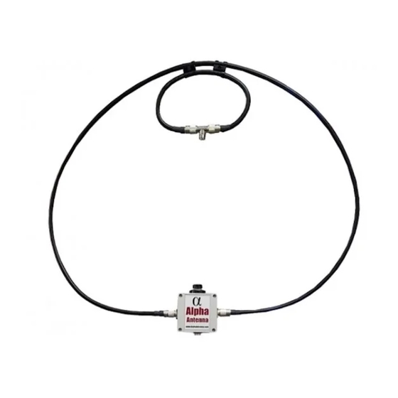
Model – Alpha Loop
Operating Manual, Version 4.1, June 14, 2018
Operation
The Alpha Loop is designed to operate from 10 through 40 meters, which includes the 10, 12,
15, 17, 20, 30, & 40 Meter amateur radio bands, where it is rated at 50W CW, 25W Digital, and
between 98 to 60W PEP SSB per the following chart no matter where your Mic Gain is set.
With a properly adjusted Mic Gain this system will handle 100W PEP SSB (See Page 2 'Tuning').
Excess RF Exposure Warning
In the United States, the Federal Communications Commission has established guidelines for
human exposure to Radio Frequency (RF) electromagnetic fields. The commission's
requirements are detailed in parts 1 & 2 of the FCC's rules and regulations {47 CFR, 1.1307(b),
1.1310, 22.1091, 2.1093}. It is the responsibility of the owner/operator of this device to follow
all applicable warnings and precautions regarding human exposure to RF fields. Additional
references: http://www.arrl.org/rf‐exposure
Page 1
Advertisement
Table of Contents

Related Manuals for Alpha Antenna Alpha Loop


Summary of Contents for Alpha Antenna Alpha Loop
- Page 1 ____________________ Model – Alpha Loop Operating Manual, Version 4.1, June 14, 2018 Operation The Alpha Loop is designed to operate from 10 through 40 meters, which includes the 10, 12, 15, 17, 20, 30, & 40 Meter amateur radio bands, where it is rated at 50W CW, 25W Digital, and between 98 to 60W PEP SSB per the following chart no matter where your Mic Gain is set. With a properly adjusted Mic Gain this system will handle 100W PEP SSB (See Page 2 ‘Tuning’). Excess RF Exposure Warning In the United States, the Federal Communications Commission has established guidelines for human exposure to Radio Frequency (RF) electromagnetic fields. The commission’s requirements are detailed in parts 1 & 2 of the FCC’s rules and regulations {47 CFR, 1.1307(b), 1.1310, 22.1091, 2.1093}. It is the responsibility of the owner/operator of this device to follow all applicable warnings and precautions regarding human exposure to RF fields. Additional references: http://www.arrl.org/rf‐exposure Page 1...
- Page 2 Assembly Locate the Selfie Stick: Locate the grey Alpha Match box: Extend the selfie Screw the selfie stick onto stick and note the the screw located on the screw hole on the top of the grey Alpha bottom (Figure 1). Match box (Figure 2). Feel The screw on top free to turn till the center of the grey Alpha loop is aligned. You might Match box will need to hold the nut under screw into this the selfie‐stick with pliers if hole. it is overtightened. Locate the large Coaxial Loop element: Secure the Large Coaxial elements: Straighten this outer Take note of the approximate Coaxial Loop Element center for the Outer loop. Place to form an approximate the center of the large coaxial circle that is slightly element over the top of the selfie larger than 3 feet in stick, then the PL‐259 ends on the diameter. larger outer loop will be near the Alpha Match box. Secure the outer and the smaller inner loop using the nylon clips, which just turn and snap on. Attach PL259 connectors: Tuning: 98‐60W SSB and 50W CW/25W Digital Tuning ...
Need help?
Do you have a question about the Alpha Loop and is the answer not in the manual?
Questions and answers