
Related Manuals for Alpha Antenna DX-Mil


Summary of Contents for Alpha Antenna DX-Mil
- Page 1 Manual for the DX-Mil (Model 2-30MHZ) HF Antenna Manufactured by: Alpha Antenna 1.888.482.3249 Website: http://AlphaAntenna.com User Guide Version 1.7 September 18, 2019 Page 1...
-
Page 2: Table Of Contents
Table of Contents Safety Information ..............................3 Excess RF Exposure Warning ..........................4 SECTION 1 – Concept of Operation......................... 5 SECTION 2 – System Overview..........................7 Physical Description ..............................7 Equipment Characteristics ............................7 SECTION 3 – Technical Data............................ 8 Leading Specifications............................. -
Page 3: Safety Information
Safety Information When installing or operating this antenna or any other antenna/tower, please observe the following safety tips. High voltages are present when transmitting, no matter how much or little power is applied. Do not touch any part of the antenna while transmitting. NOTE –... -
Page 4: Excess Rf Exposure Warning
Guidelines for Human Exposure to Radio frequency Electromagnetic Fields directly concerns the use and operations of all Alpha Antenna systems. This bulletin establishes safe operating distances from antennas associated power levels in order to permit the operator and persons who may be impacted by operation to exist in a safe environment. -
Page 5: Section 1 - Concept Of Operation
SECTION 1 – Concept of Operation The Model DX-Mil is a limited space transportable base antenna that operates over the 2 to 30 MHz bands to link wideband HF communications equipment using short range (ground wave), medium range (sky wave), and long haul RF patterns as shown in the Appendices. - Page 6 Because it is highly desirable to have minimum height and weight for transportable or tactical antennas, the immediate problem becomes one of determining the minimum effective antenna height required. In order to determine the required antenna height, a minimum acceptable level of performance is established as necessary to permit communications.
-
Page 7: Section 2 - System Overview
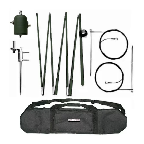
SECTION 2 – System Overview Physical Description Physically this antenna consists of: 1 –Padded Black Case, 1 – 6 foot Anodized Black Steel Tripod (NOTE – Guying the tripod is recommended, and for permanent deployments, a user supplied mast that is 6 feet high can be used), 1 –... -
Page 8: Section 3 - Technical Data
SECTION 3 – Technical Data Leading Specifications Leading Specifications and equipment for the Alpha DX-Mil antenna are listed in Tables 1-2 to 1-4. Personnel should become thoroughly familiar with data and procedures contained in the entire technical manual before working on or using the antenna. The antenna system should be guyed when winds are present and a user supplied mast that is 6 feet high is required for permanent deployments. -
Page 9: Swr
The following analysis is certified as accurate using a calibrated AIM 4300 from Array Solutions and is checked for redundancy using a calibrated Rig Expert AA-54. Equipment is connected via a barrel connector with no coax. Once coax is connected, operators may find that a choke balun is needed. SWR Analysis Page 9... -
Page 10: Pattern
Pattern After deployment, the DX-Mil has four sloped Horizontal wire NVIS element placed at 90 degrees from each other. This placement enables a take off angle that is sloped towards each horizon, and that in turn enables long haul signal patterns. Then the placement of these same elements closer to the ground enables the sky wave pattern when the signals are reflected off the ground that by design is close to the Horizontal elements. -
Page 11: Gain
By design, the DX-Mil places both its’ Horizontal and Vertical elements close to the ground to take advantage of ground gain. The results are the gain figures that occur above the Brewster angle, which is where no signal is present and where the ground gain has come from. -
Page 12: Section 4 - Site Selection
SECTION 4 – Site Selection Antenna Placement For maximum antenna operating efficiency, the Alpha DX-Mil antenna should be placed in the center of a clear area. Installation of the antenna near any tall metal object or under heavy foliage should be avoided. Under no circumstances should structures come in contact with the antenna. -
Page 13: Appendices
Appendices Appendix A – Installation Appendix A.1 – Antenna Fully Assembled Component Measurements Components Assembly Axial radius = 30 x 30 feet T1 = Tripod for temporary or a user supplied mast that Footprint = 60 feet x 60 feet is 6 feet high is required for permanent deployments. -
Page 14: Appendix B - Patterns
Appendix B – Patterns Appendix B.1 – Elevation/Azimuth Patterns Page 14... - Page 15 Stop Patterns Page 15...
-
Page 16: Support
Support If you have any questions or problems with your Alpha Antenna, please contact us. You can reach us via: Email – support@AlphaAntenna.com Phone – 1-888-482-3249 Web – www.AlphaAntenna.com Our mailing address is: Alpha Antenna 112 East Commercial Street Pleasant Hill, MO 64080...
Need help?
Do you have a question about the DX-Mil and is the answer not in the manual?
Questions and answers