Table of Contents
Advertisement
OPERATOR’S MANUAL
p
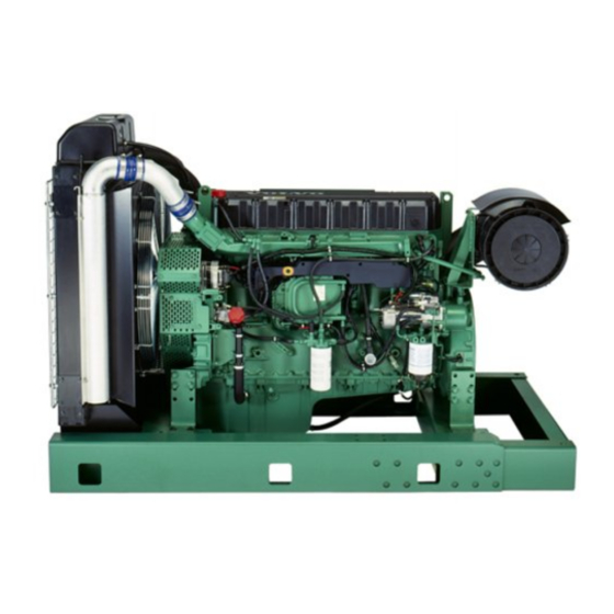
Generating set and industrial engines
12 litre (EDC III)
Doosan purchased Bobcat Company from Ingersoll-Rand Company in
2007. Any reference to Ingersoll-Rand Company or use of trademarks,
service marks, logos, or other proprietary identifying marks belonging
to Ingersoll-Rand Company in this manual is historical or nominative
in nature, and is not meant to suggest a current affiliation between
Ingersoll-Rand Company and Doosan Company or the products of
either.
Revised (10-12)
Advertisement
Table of Contents


Need help?
Do you have a question about the TAD1240GE and is the answer not in the manual?
Questions and answers