
Related Manuals for Volvo TAD734GE


Summary of Contents for Volvo TAD734GE
- Page 1 Users guide and maintenance manual 7747302 (English03-2007) 33522069101_0_1...
- Page 3 OPERATOR’S MANUAL TAD734GE (EMS 2)
- Page 4 This is not by chance. After more than 90 years of producing engines the name Volvo Penta has come to symbolize reliability, technical ingenuity, first-class perfor- mance and longevity.
-
Page 5: Table Of Contents
Table of contents Safety information ..........2 Maintenance schedule ........26 Safety precautions for operation and maintenance..........3 Maintenance ............28 Engine, general ........... 28 Introduction ............6 Lubrication system ..........30 Environmental care ..........6 Cooling system ........... 33 Running in ............. -
Page 6: Safety Information
If there is still something which is unclear or you are unsure of, please contact your Volvo Penta dealer for assistance. This symbol is used in the instruction book and on the product, to call your attention to the fact that this is safety information. -
Page 7: Safety Precautions For Operation And Maintenance
Never do a job if you are not entirely sure about how or stop the engine. In a diesel engine, it can also to do it. Please contact your Volvo Penta dealer and cause the injection pump to bind and the engine to ask for assistance instead. -
Page 8: Fire And Explosion
Components in fuel systems and electrical systems the engine should be used. Always check that the lift- on Volvo Penta engines are designed and manufac- ing devices are in good condition and that they have tured to minimize the risk of explosions and fire, in ac- the correct capacity for the lift (engine weight together cordance with applicable legal requirements. -
Page 9: Cooling System
Safety information Fuel System Hot Surfaces and Fluids Always protect your hands when searching for leaks. A hot engine always presents the risk of burns. Be on Fluids which leak under pressure can force their way your guard against hot surfaces: the exhaust mani- into body tissue and cause severe injury. -
Page 10: Introduction
Introduction This instruction book has been prepared to give you the greatest possible benefit from your Volvo Penta industrial engine. It contains the information you need to be able to operate and maintain the engine in a safe and propper manner. -
Page 11: Certified Engines
Warranty and Service book. Please note that AB Volvo Penta’s liability is limited to that which is stated in the Warranty and Service book. Read it carefully, as soon as possible after delivery. It contains important information about, among other things, warranty cards, sevice intervals and maintenance which, as the owner, is your re- sponsibility to know, check and execute. -
Page 12: Presentation
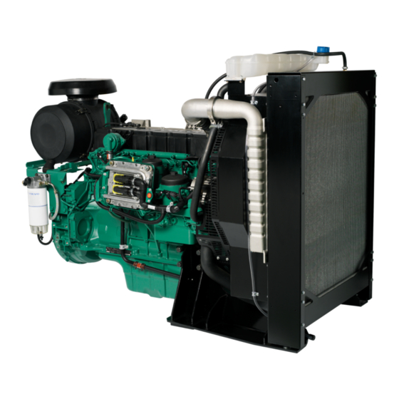
Presentation TAD734GE is a direct injection, straight, 6-cylinder engine. The engine is equipped with a “common rail” fuel injection system, IEGR (Internal Exhaust Gas Recirculation), electronically-controlled fuel management (EMS 2), turbocharger, thermostatically-controlled cooling systems and electronic speed control. Technical Description... -
Page 13: Identification Numbers
Presentation Identification Numbers Location of Engine Plates The engines are supplied with two engine plates, of which one is situated on the right side of the engine block and the other on top of the valve cover. Engine Plate 1. Engine model 7. -
Page 14: Component Location
Presentation Component Locations, TAD734GE 1. Crankcase ventilation, (sealed crank- case ventilation optional) 2. Oil Filler 3. Fuel filter 4. Common Rail unit, with safety valve and rail pressure sensor 5. Oil filter 6. Lifting eyes, (2 pcs) 7. Inlet, after charge-air cooler 8. -
Page 15: Location Of Sensors
Presentation Location of sensors NOTE! Positions may differ, depending on the engine model. 1. Proportional solenoid valve, high pres- sure pump – fuel (MPROP) 2. Coolant temperature 3. Water in fuel, (mounted on fuel pre-filter). 4. Charge air pressure and temperature 5. -
Page 16: Ems 2
Presentation EMS 2 EMS 2 (Engine Management System) is an electronic system with CAN communication (Controller Area Network) for diesel engine control. The system has been developed by Volvo and includes fuel control and a diagnostic function. Summary Fuel Management... -
Page 17: Instrument, Ems 2
Presentation Instrument, EMS 2 NOTE! All instruments are fittings. CIU – Control Interface Unit The CIU is the “translator” between the EMS 2 engine control unit and the customer’s own control panel. The CIU has two serial communication links, one fast and one slow. -
Page 18: Dcu (Display Control Unit)
DCU (Display Control Unit) The DCU (Diesel Control System) control panel is available as an accessory for the EMS (Engine Management System) electronic control system. The DCU is a digital instrument panel which communicates with the engine control unit. The DCU has a number of functions such as engine control, engine monitoring, diagnostics and pa- rameter setting. -
Page 19: Engine Data
Menus There are several sub-menus under each main menu. There is not always space for all the menu choices on the display. To scroll through the menus, use the “7” and “9” buttons on the display. Press the “SEL” button “8”... -
Page 20: Trip Reset
Preheat manual activation of preheating. When activated, the EMS system senses at start if preheating is neces- sary. For automatic preheating, refer to “Setup”/“Pre- heat on ignition” menu. NOTE! Must be activated when the temperature is be- low 0°. The preheating time is adjusted to suit the engine temperature, and can last for up to 50 seconds both before and after starting. - Page 21 Setup parameter setting in the engine’s control systems. De- pending on whether you select “Versatile” or “Genset” from “Set application”, different menus will appear un- der “Customer parameter”; see below. The parameters which can be set/selected (choice is made with the SEL button) are: •...
- Page 22 Customer parameter/Genset • Primary engine speed – selection of engine rpm, 1500 or 1800 rpm. • Preheat on ignition – activation of automatic pre- heat. The engine control system senses if pre- heating is needed and activates it directly when switched on.
- Page 23 Display setting settings for the display. Adjustment is made with the “7” and “9” buttons; see DCU panel illustration. • Set contrast (%) – contrast setting. • Set backlight time (sec) – sets the time (in sec- onds) for the display backlight; the backlight switches off when the panel is not in use.
-
Page 24: Starting The Engine
Starting the engine Make it a habit to check the engine and engine room before starting. This will help you to discover quickly if anything abnormal has happened, or is about to happen. Also check that instruments show normal values after starting. Before Starting •... -
Page 25: Start Routine (Dcu)
Starting the engine Start routine (DCU) The preheating time is adjusted to suit the engine temperature, and can continue for up to 50 seconds both before and after starting. The starter motor connection time is maximized to 30 seconds. After that, the starter motor circuit is cut for 80 seconds to protect the starter motor against over- heating. -
Page 26: Starting In Extreme Cold
Preheat the coolant with a separately installed electric engine heater. In extreme cases, a diesel-burning en- gine heater may be needed. Ask your Volvo Penta dealer for advice. IMPORTANT! Make sure that the cooling sys- tem is filled with a glycol mixture. Refer to the “Maintenance, cooling system”... -
Page 27: Never Use Start Spray
Starting the engine Never use start spray WARNING! Never use start spray or similar prod- ucts as a starting aid. They may cause an explo- sion in the inlet manifold. Injury may also result. Starting with auxiliary batteries WARNING! Batteries (especially auxiliary batter- ies) contain oxyhydrogen which is highly explo- sive in contact with air. -
Page 28: Running
Operation Correct operating technique is very important for both fuel economy and engine life. Always let the engine warm up to normal operating temperature before full power is demanded. Avoid sudden throttle openings and operation at high engine rpm. Operation at low load Check instruments Check all instruments immediately after starting, and Avoid long-term operation at idle or at low load, since... -
Page 29: Stopping The Engine
Engine shutdown During longer shutdown periods, the engine must be run and warmed through at least once every 2 weeks. This prevents corrosion in the engine. If the engine is expected to remain unused for two months or more, preservation must be carried out: Ses the chapter “Shutdown”. -
Page 30: Maintenance Schedule
It contains instructions on how to carry out the work safely and correctly. IMPORTANT! When both running hours and calendar periods are specified, carry out the maintenance item at whichever time is reached first. Maintenance items marked must be carried out by an authorized Volvo Penta workshop. Daily, before first start •... - Page 31 Maintenance schedule Every 125-500 running hours or at least every 12 months • Engine oil and oil filter, change 1) 2) ..............page 32 Oil change intervals vary, depending on oil grade and sulfur content of the fuel. Refer to “Lubrication system”. The oil filter must be replaced at every oil change.
-
Page 32: Maintenance
Maintenance This chapter describes how the prescribed maintenance items must be carried out. Read the instructions carefully before starting work. The times when maintenance items are to be carried out are set out in the previous chapter: Maintenance schedule. WARNING! Read through the safety precautions for maintenance and service in the “Safety information” chapter before starting work. - Page 33 Maintenance Drive belt, inspection/changing Inspection should be done after running, when the belts are hot. It should be possible to press the alternator belts and drive belts down about 3-4 mm between the pulleys. The alternator belts and drive belts have automatic belt tensioners and do not need to be adjusted.
-
Page 34: Lubrication System
Lubrication oil must comply with both requirements. Note API: CG-4 or CH-4 can be approved in markets outside Europe (instead of ACEA E3). VDS = Volvo Drain Specification ACEA = Association des Constructeurs Européenne d’Automobiles API = American Petroleum Institute... - Page 35 Maintenance Viscosity Select the viscosity from the adjacent table, for the ap- propriate continuous ambient air temperature. *Denotes synthetic or semi-synthetic oils Oil change volume Refer to the “Technical Data” chapter Oil level. Inspection Make sure that the oil level is between the MIN and MAX marks.
- Page 36 Maintenance Oil filter. Change Change the oil filters during each oil change. WARNING! Hot oil and hot surfaces can cause burns. 1. Drain the oil according to the instructions in “En- gine oil Replacement”. NOTE! Position a suitable vessel underneath the filter to avoid oil spillage.
-
Page 37: Cooling System
Volvo Penta. For complete engine protection the coolant should contain good quality ethylene glycol of a suitable chemical composition. Using an anti-corrosion mixture exclusively is not permitted in Volvo Penta engines. Never use water alone as the coolant. -
Page 38: Water Quality
-28 °C. (Using 60 % glycol lowers the freezing point to -54 °C.) Never mix more than 60 % concentrate (Volvo Penta Coolant) in the cooling liquid, since this would give reduced cool- ing effect and increase the risk of overheating and frost damage. - Page 39 Maintenance Coolant. Checking and filling WARNING! Do not open the filler cap when the engine is hot, except in emergencies. Steam or hot fluid could spray out. Check the coolant level daily before starting. Top the coolant up as necessary. The level should be about 50 mm below the sealing plane of the filler cap, or between the MIN and MAX markings, if a separate expansion tank is installed.
- Page 40 Maintenance Coolant. Draining Before draining, stop the engine and unscrew the filler cap. WARNING! Do not open the filler cap when the engine is hot, except in emergencies. Steam or hot fluid could spray out. WARNING! Glycol is poisonous (dangerous to ingest).
- Page 41 1. Empty the cooling system. Refer to “Cooling sys- tem, draining”. 2. Put a hose into the expansion tank filling hole and flush with clean water, according to Volvo Penta specifications – refer to section “Water quality” – until the water draining out is completely clear.
-
Page 42: Fuel System
Maintenance Fuel System Use only recommended grades of fuel in accordance with the fuel specification below. Always observe the great- est cleanliness during re-fueling and work on the fuel system. Should dirt get into the system, it may cause injec- tor failure. - Page 43 Maintenance Fuel pre-filter, draining water 1. Stop the engine and open the fuel tap. 2. Position a suitable vessel underneath the filter. 3. Open the drain valve (1) and drain off fuel/water. 4. Unscrew the water reservoir from the filter car- tridge by turning it clockwise.
- Page 44 Maintenance Purging the fuel system The fuel system must be vented after a filter change, if the fuel tank has been run dry, or after a long-term stoppage. 1. Position a suitable vessel underneath the fuel filter. 2. Open the vent screw (1). 3.
-
Page 45: Electrical System
IMPORTANT! Never disconnect the current with the main switch when the engine is running. Electrical connections Check that electrical connections are dry, free from oxide and that they are securely tightened. Spray these connections as necessary with water-repellent spray (Volvo Penta universal oil). - Page 46 Maintenance Battery. Maintenance WARNING! Fire and explosion hazard. Batteries must never be exposed to naked flames or sparks. WARNING! Never confuse the positive and neg- ative poles on the batteries. Risk of arcing and explosion. WARNING! Battery electrolyte is highly corro- sive.
- Page 47 Maintenance Batteries, charging WARNING! Explosion risk! Hydrogen is given off when batteries are charged. This forms an explo- sive mixture with air. A short circuit, open flame or spark could cause a violent explosion. Venti- late well. WARNING! Battery electrolyte is highly corro- sive.
-
Page 48: Shutdown
For this reason, we have compiled a check list covering the most important points. Before shutting down for long periods, an authorized Volvo Penta workshop carry out an inspection. Have any faults and defects remedied, so that the equipment is in working order the next time it is started. -
Page 49: Restoration
Shutdown Returning to service • • Close drain taps and fit drain plugs if necessary. Remove any covers from the engine, air filter and exhaust pipe. • Check coolant level. Top up as necessary. • Top the engine up with the correct grade of oil, if •... -
Page 50: Troubleshooting
A number of symptoms and possible causes of engine malfunctions are described in the table below. Always con- tact your Volvo Penta dealer if any problems occur which you cannot solve by yourself. WARNING! Read the safety precautions for maintenance and service in the chapter “Safety precautions” be- fore starting work. -
Page 51: Diagnostic Function
Diagnostic Function The diagnostic function monitors and checks that the EMS 2 system is functioning normally. The diagnostic function has the following tasks: • Detecting and locating malfunctions • Reporting detection of malfunctions • Providing guidance when troubleshooting Fault messages If the diagnosis function detect a disturbance in the •... -
Page 52: Operation
Diagnostic Function Operation When a malfunction has occurred and the diagnostic Reading fault codes via the DU system has generated one or more fault codes, these (Display Unit) are deciphered differently depending on the equipment Depending on the severity of the fault the text, either used;... - Page 53 Reading fault codes via the diagnostic Reading the fault codes via an “Easy lamp on the instrument panel, CIU link” instrument (only with a CIU) When the system has discovered a malfunction, the When the system has discovered a malfunction, it is diagnostic lamp starts to flash.
-
Page 54: Fault Codes
Fault codes WARNING! Read the safety precautions for maintenance and service in the chapter “Safety information” before starting work. NOTE! Reading the fault codes below, such as Code 2.1, PID/SPN 97, where 2.1 is a flash code indicated by a flashing diagnostic lamp. - Page 55 Fault codes Code 2.5, SID 21/SPN 636 Code 2.9, PID/SPN 97 Engine rpm sensor, cam disc Indicator for water in fuel Reason: Reason: • No signal. • Short circuit. • Abnormal frequency. • Open circuit. • Fault in sensor. • Fault in indicator.
- Page 56 Fault codes Code 3.3, PID/SPN 110 Code 3.6, PID/SPN 94. Fuel pressure sensor Coolant temperature sensor Reason: Reason: • Short circuit to positive (+) or negative (-). • Short circuit to positive (+) or negative (-). • Open circuit. • Open circuit.
- Page 57 Fault codes Code 4.6, PPID 3/SID 39/SPN 677 Code 5.3, PPID 6/SPN 520195. Stopp input, CIU Start output/Starter motor relay Reason: Reason: • Short circuit to negative (-). • Short circuit to positive (+) or negative (-). • Open circuit. •...
- Page 58 Fault codes Code 6.5, SID 231/SPN 639/2017/PSID 201 Code 6.1, PID/SPN 110. Coolant temperature Data link (CAN), EMS 2 Reason: Reason: • Coolant temperature is too high. • Internal fault in control unit. Reaction: Reaction: • Engine control unit reduces engine power (unless •...
- Page 59 Fault codes Code 7.1, SID 1/SPN 651 Code 7.3, SID 3/SPN 653 Injector, cylinder #1 Injector, cylinder #3 Reason: Reason: • Electrical fault. • Electrical fault. • Faulty compression or injector. • Faulty compression or injector. Reaction: Reaction: • Engine runs on 5 cylinders. •...
- Page 60 • Engine contril unit limits engine power. • Reduced performance. Action: Action: • Contact an authorized Volvo Penta workshop. • Check that the unit injector cables are not dam- Code 8.3, PSID 96/SPN 1239 aged. Pressure in distribution manifold •...
- Page 61 Fault codes Code 9.3, SID 232/221/SPN 620/1079/1080 Code 8.3, PID/SPN 164. Injection pressure Voltage supply to sensor Reason: Reason: • Faulty fuel supply. • Short circuit. • Faulty fuel pump. • Fault in one of sensors. • Faulty cables. Reaction: •...
- Page 62 Fault codes Code 9.9, SID 240/SPN 639, Memory fault in EMS Reason: • Memory fault in engine control unit (EMS). Reaction: • Engine might not start. Action: • Re-program the unit. Code 9.9, SID 254/SPN 629. Control unit EMS Reason: •...
-
Page 63: Technical Data
Technical data General Type designation TAD734GE Power Refer to the sales literature Torque Refer to the sales literature No. of cylinders Bore Stroke, mm Cylinder volume, dm 7.15 Weight*, app., kg Weight, app., kg Weight*, wet, kg Weight, wet (GenPac), kg... -
Page 64: Lubrication System
Technical data Lubrication System Oil grade ..............Refer to the “Maintenance, lubrication system” chapter Oil change volume, including change of filters: oil pan, standard ............. 29 liter (7.7 US gallon) Oil pressure with engine oil at operating temperature (min 120 °C) At rated engine rpm ............ -
Page 65: Cooling System
Cooling System Type ................Pressurized, sealed Pressure valve, max. opening pressure: ....120 kPa (17.4 psi) Volume (engine) TAD734GE: ............8 liter (2.11 US gal) Thermostat Quantity and type ............1 pc piston thermostat Opening temperature ..........83 °C (181 °F) Fully open at .............. - Page 66 Notes ..............................................................................................................................................................................................................................................................................................................................................................................................................................................................................................................................................................................................................................................................................................................................................................................................................................................................................................................................................................................................................
- Page 67 ✂ Yes please, I would like an operator’s manual in English at no charge. Publication number: 7747302 Post or fax this coupon to: Document & Distribution Center Name Order Department ARU2, Dept. 64620 Address SE-405 08 Göteborg Sweden Fax: +46 31 545 772 Orders can also be placed via the Internet: http://www.volvopenta.com/...
- Page 68 ✂ Sí gracias, deseo recibir gratuitamente un libro de instrucciones en español. Número de publicación: 7747305 Franquear o enviar fax a: Document & Distribution Center Nombre Order Department ARU 2, Dept. 64620 Dirección SE-405 08 Göteborg Suecia Fax: +46 31 545 772 El pedido puede hacerse tam- bién por internet: http://www.volvopenta.com/...
- Page 69 ✂ Ja graag, Ik wil kosteloos een instructieboek in het Nederlands ontvangen. Publicatienummer: 7747308 Stuur of fax de coupon naar: Document & Distribution Center Naam Order Department ARU 2, Dept. 64620 Adres SE-405 08 Göteborg Zweden Fax: +46 31 545 772 U kunt ook bestellen via internet: http://www.volvopenta.com/...
- Page 70 ✂ Íáé, Èá Þèåëá Ýíá áíôßôõðï ôïõ åã÷åéñéäßïõ ÷ñÞóçò óôçí áããëéêÞ ãëþóóá ÷ùñßò êáìéÜ ÷ñÝùóç. Áñéèìüò Ýêäïóçò: 7747310 Ôá÷õäñïìÞóôå áõôü ôï êïõðüíé ¼íïìá óôçí ðáñáêÜôù äéåýèõíóç Þ óôåßëôå ôï ìå öáî óôïí ðáñáêÜôù áñéèìü öáî: Äéåýèõíóç Document & Distribution Center Order Department ARU2, Dept.
Need help?
Do you have a question about the TAD734GE and is the answer not in the manual?
Questions and answers
I want to know about injector copper sleeve.what is it function? how to remove?when condition should replace
The injector copper sleeve in the Volvo TAD734GE engine seals the injector against the cylinder head to prevent combustion gases and coolant from leaking.
Removal:
To remove the injector sleeve, first remove the injector. Then use a special puller tool to extract the sleeve from the cylinder head.
Replacement:
Replace the sleeve if it is damaged, leaking, or if a new injector does not seal properly. Always ensure the sealing washers are also removed and replaced.
This answer is automatically generated