Table of Contents
Advertisement
Advertisement
Table of Contents

Related Manuals for Volvo TAMD74C


Summary of Contents for Volvo TAMD74C
- Page 1 OPERATOR’S MANUAL TAMD74C/L/P...
- Page 2 This operator’s manual is also available in the following languages: Diese Betriebsanleitung ist auch auf Dit instructieboek kan worden besteld Deutsch erhältlich. in het Nederlands. Ein Bestellcoupon ist am Ende der Betriebs- De bestelcoupon vindt u achter in het instruc- anleitung zu finden.
- Page 3 Welcome aboard Volvo Penta marine engines are used all over the world today. They are used in all possible operating conditions for professional as well as leisure purposes. That’s not surprising. After more than 90 years as an engine manufacturer and after delivering over 500,000 marine engines, the Volvo Penta name has become a symbol of reliability, technical innovation, top of the range performance and long service life.
-
Page 4: Table Of Contents
Changing control position ........26 Manoeuvering ............27 Emergency shifting ..........28 Forced propeller rotation ........28 Accessories ............28 © 2000 AB VOLVO PENTA All rights to changes or modifications reserved. Printed on environmentally friendly paper. (Cover: Department of transport (shipping), license 9809095) -
Page 5: Safety Information
Read the Operator’s Manual carefully before operating or servicing the engine. If anything is unclear please contact your Volvo Penta dealer for assistance. This symbol is used in the book and on the engine to make you aware of safety information. -
Page 6: Boat Travel
Safety information Safety regulations for boat trips The new boat Filling fuel Read operator’s manuals and other information ac- There is a risk of fire and explosion when filling fuel. companying the new boat thoroughly. Accustom Smoking is prohibited and the engine must be turned yourself with handling the engine, controls and other off. - Page 7 Safety information Carbon monoxide poisoning Most modern boats, however, are designed in such a When a boat is moving forward, it will cause a certain way that this problem is very rare. If suction should vacuum to form behind the boat. In unfortunate cir- arise anyway, do not open hatches or portholes at the cumstances, the suction from this vacuum can be so fore of the boat.
-
Page 8: Maintenance And Service
All fuel, most lubricants and many chemicals are Never perform a task unless you are absolutely sure flammable substances. Always read and follow the di- how it is to be carried out, call your Volvo Penta deal- rections on the packaging. er for assistance instead. - Page 9 Safety information Hot surfaces and fluids Fuel system Always protect your hands when carrying out leak de- A hot engine always involves risk for burn injuries. tection. Escaping fluids under pressure can pierce Take care with hot surfaces. E.g.: exhaust manifold, bodily tissue and cause serious injury.
-
Page 10: Introduction
Introduction The Operator’s Manual has been produced to give you the greatest benefit of your Volvo Penta marine engine. It contains the information necessary to handle and maintain your engine in a safe and correct manner. We would like you to read this Operator’s Manual thoroughly and learn how to handle the engine, controls and other equip- ment in a safe manner before casting off for your maiden voyage. -
Page 11: Certificated Engines
Warranty liability will otherwise be declined completely or fully by AB Volvo Penta. Get in touch with your Volvo Penta dealer if you have not received a Warranty and Service Book or a copy of the warranty card. -
Page 12: Identification Numbers
Introduction Identification numbers Type plates with identification numbers can be found on the engine and transmission. This information must al- ways be used as a reference when ordering service and spare parts. Similar plates can probably be found on your boat and its equipment. Make a note of the information in the space below and make a copy of this page so the information is available even if the boat should be stolen. -
Page 13: Presentation
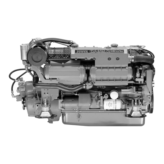
Presentation TAMD74C-B, TAMD74L-B and TAMD74P-B are in-line, direct injection, 6-cylinder, marine diesel engines spe- cially developed for fast planing and semi-planing craft. The engines are equipped with electronic fuel control (EDC*), turbocharger, charge air cooler, heat exchanger for thermostatically controlled fresh water cooling and electronic engine speed control and shifting. -
Page 14: What Is Edc
What is EDC EDC stands for Electronic Diesel Control. It is an electronic system for marine diesel engine control. The system has been developed by Volvo Penta and covers fuel control, diagnostic function and electronic engine speed control and shifting. -
Page 15: Orientation
Presentation Orientation TAMD74C-B, TAMD74L-B, TAMD74P-B 3 4 5 1. Fuel filters 2. EDC control module 3. Oil filler cap 4. Coolant filler cap 5. Injection pump 6. Distribution box with semi-automatic fuses 7. Turbocharger 8. Water cooled exhaust pipe elbow (option) 9. -
Page 16: Instrumentation
Instrumentation This chapter describes the Volvo Penta instruments that are available for your engine. Note that tachometer, oil gauge, temperature gauge, charge gauge, starting switch, etc., that are shown here as panel mounted may be mounted separately in some boats. -
Page 17: Control Panels
Instrumentation Control panels Control panels for the main control position and auxil- iary control position. 1. Siren for acoustic alarm that sounds if one of the warning lamps comes on. 2. Press button for instrument illumination. 3. Press button for testing and acknowledging alarms (see “Warning displays”... -
Page 18: Starting Switch
Instrumentation Starting switch Delivered with the starter keys is a plate containing the key code required when ordering additional start- er keys. Do not keep the code where unauthorized persons can access it. S = Stop position. 0 = Key can be inserted and removed. I = Voltage on (drive position). - Page 19 Instrumentation Control panel EDC (Type I) If the boat has a single engine there are three buttons in the control panel. If the boat has two engines there are six buttons in the control panel. Each button has an LED which indicates the present selection or status. Note that certain buttons and LEDs are duplicated on the control panel for two engines.
- Page 20 Instrumentation Control panel EDC (Type II) If the boat has a single engine there are three buttons in the control panel. If the boat has two engines there are six buttons in the control panel. Each button has an LED which indicates the present selection or status. Note that the neutral and diagnostic buttons are duplicated on the control panel for two engines.
-
Page 21: Controls
Controls This chapter describes the controls available from Volvo Penta. If your boat is equipped with controls which are not described here and you feel uncertain about the function please contact the dealer you purchased the boat from. Single lever control. Electronic... -
Page 22: Dual Lever Control
Controls Friction brake The control has a friction brake which can be adjusted as necessary to provide lighter or heavier lever action. Adjusting the friction brake: 1. Stop the engine. 2. Mover the control lever forwards so that the groove in the hub of the control lever is accessible. -
Page 23: Starting The Engine
Starting the engine Make a habit of “visually” inspecting the engine and engine room before starting This will help you to quickly de- tect abnormalities that have occurred or are about to occur. Make sure instruments and warning displays indi- cate normal values after starting the engine. -
Page 24: Starting Procedure
Starting the engine Starting procedure 1. Disengage the reverse gear Put the control lever into neutral and idle on all control positions Dual lever control: Make sure that the accelerator is in idle position (all the way back). 2. Switch on the power Turn the start key to position “I”... - Page 25 Starting the engine Start using the start button Press the start button. Release the button immediately after the engine has started (note that when starting from the alternative control position, the starter key at the main control position must be turned to “I”). Overheating protection: If the starter motor is engaged for the maximum en- gagement time (30 seconds), the starter motor circuit is...
-
Page 26: Operation
Operation It is important to learn how to operate the engine, controls and other equipment safely and properly before setting off on a maiden voyage. Avoid violent and unexpected changes in course and gear engagement. There is a risk that someone aboard will fall over or overboard. WARNING! A rotating propeller can cause serious injury. -
Page 27: Diagnostic Information
There could be several reasons for the engine failing to reach the wide open throttle range, see the chapter “Trou- bleshooting”. Use a propeller with a greater pitch if the en- gine speed exceeds the wide open throttle range. Get in touch with your Volvo Penta dealer for advice. -
Page 28: Synchronizing Engine Speed
Operation Synchronizing the engine speed When driving with twin engines, both the operating econo- my and comfort can be increased if the engines are oper- ating at the same engine speed (RPM). If the synchronization function is activated, the engine speed (RPM) of the starboard engine is automatically ad- justed to that of the port engine if: 1. -
Page 29: Manoeuvering
Operation Manoeuvering The chapter contains functional descriptions of the con- trols available from Volvo Penta. The reverse gear must be engaged at low idling speed. There must be a brief pause after engaging reverse gear before increasing the engine speed. The pause must be approximately two seconds long to ensure the reverse gear clutch plates are properly engaged. -
Page 30: Emergency Shifting
Operation Emergency shifting If shifting is not possible with the control, the Twin Disc and ZF gears (intended for electronic shifting) can be en- gaged manually for forward movement. See the “Trouble- shooting” chapter for additional information. If the boat has more control positions, it may be pos- sible to operate the reverse gear from this/these. -
Page 31: Stopping The Engine
Stopping the engine Let the engine run at low idling speed (in neutral) for at least three minutes before turning it off. This will keep the engine temperature in balance and prevent it boiling. IMPORTANT! The procedure described above is especially important if the engine has been run hard and/ or exerted to heavy loads. -
Page 32: Cold Weather Precautions
Stopping the engine Anti-freezing measures If the engine room cannot be protected from frost, the sea- water system must be drained and the coolant in the freshwater system must contain sufficient anti-freeze to prevent it from freezing. Refer to chapter Maintenance “Seawater system”... -
Page 33: Maintenance Schedule
Maintenance schedule Your Volvo Penta engine and associated equipment is designed to provide high operational reliability and long service life. They are constructed to withstand the marine environment while also affecting it as little as possible. Preventive maintenance in accordance with the maintenance schedule will ensure that it retains these qualities and avoid unnecessary operational disturbances. - Page 34 Maintenance schedule Every 100 operating hours / at least every 12 months Crankcase ventilation. Change filters ............page 35 Engine oil. Change ..................page 38 Oil filter/By-pass filter. Change ..............page 39 The oil change interval varies depending on oil grade and sulphur content of the fuel. See “Maintenance: Lubricating system”.
- Page 35 Maintenance schedule Every 1000 operating hours / at least every 24 months Valve clearances. Check/Adjust ..............not shown Every 2000 operating hours / at least every 24 months Injectors. Pressure test ................not shown Every 12 months Coolant. Change ..................page 43 Seawater pump.
-
Page 36: Maintenance
Maintenance This chapter describes how to carry out the specified maintenance points. Read the instructions carefully before starting work. Maintenance intervals are contained in the previous chapter: Maintenance schedule WARNING! Read the safety precautions for maintenance and service in the chapter: Safety Information, before starting work. - Page 37 Maintenance: Engine, general Crankcase ventilation. Change filter Replace filters(2) earlier than recommended if air and oil mixture begins to come out of the valve (1). IMPORTANT! Change both filters at the same time. 1. Dismantle the filter (2) by screwing it anti-clock- wise.
- Page 38 Maintenance: Engine, general Air filter. Changing 1. Remove the old filter. Be careful to ensure that no contamination gets into the engine. 2. Install a new filter and tighten the hose clamps. IMPORTANT! Scrap the old filter. It must not be cleaned.
-
Page 39: Lubricating System
If the sulphur content in the fuel exceeds 1.0 wt.%, an oil with TBN14–20 must be used (TBN=Total Base Number) The oil must be changed at least once a year = Volvo Drain Specification ACEA = Association des Constructeurs Européenne d'Automobiles = American Petroleum Institute −... - Page 40 Maintenance: Lubricating system Engine oil. Check level The oil level must be within the marked range on the dipstick and must be checked daily before starting the first time. Engine oil. Filling Top up the oil through the filler opening (1) in the ven- tilation cover.
- Page 41 Maintenance: Lubricating system 4. Fill up with oil to the correct level. 5. Start the engine and allow it to idle. Check that the low oil pressure warning lamp goes out and that there is no leakage by the filters. WARNING! Approaching or working with a running engine is a safety risk.
-
Page 42: Freshwater System
In its standard version, the engine is fitted with an internal freshwater system. Volvo Penta also supply engines with the cooling system prepared for external cooling, e.g. keel cooling. - Page 43 Maintenance: Freshwater system Anti-freeze mixture When there is risk of freezing, a mixture of 50% Volvo Penta anti-freeze (glycol) and 50% water (complying with ASTM D4985) must be used. This mixture will protect against freezing down to approx. –40°C (–40°F) and is to be used all year round.
- Page 44 Maintenance: Freshwater system Coolant level. Check WARNING! Never open the pressure cap when the engine is warm. Steam or hot fluid may spurt out. The level of the coolant should be approx. 5 cm (2 in.) below the top of the filler pipe. If an external expan- sion tank is used the level should be between the MIN and MAX marks on its side.
- Page 45 Maintenance: Freshwater system 5. When the coolant is free of air bubbles, close the ventilation cocks. 6. Cease filling when the correct level is attained. 7. Start the engine and run it until it reaches operat- ing temperature. IMPORTANT! The engine must not be started before the system has been bled and filled.
- Page 46 Maintenance: Freshwater system Freshwater system. Flushing The system should be flushed before changing cool- ant to avoid inferior cooling performance due to de- posits in the cooling system. IMPORTANT! Certain parts of the system are made of light alloy. Chemical additives must therefore not be used when cleaning.
-
Page 47: Seawater System
Maintenance: Seawater system Seawater system The seawater system is the engine’s external cooling system. The seawater pump draws in water via the seawa- ter intake and pump it on through the charge air cooler, heat exchanger and the reverse gear oil cooler. The sys- tem is protected against galvanic corrosion by zinc anodes located in the charge air cooler, heat exchanger and the reverse gear oil cooler. - Page 48 Maintenance: Seawater system Impeller. Check/Change WARNING! Risk of water entering. Close the seawater cock before starting work on the sea- water system. In some installations, it can be easier to first remove the sea water pump from the engine (see next chap- ter) and then change the impeller.
- Page 49 Maintenance: Seawater system Seawater system. Drain To prevent the system from bursting during cold weather the seawater system must be drained when there is a risk of freezing WARNING! Risk of water entering. Close the seawater cock before starting work on the sea- water system.
- Page 50 Maintenance: Seawater system Seawater filter. Check/Clean The seawater filter is an accessory and is available in two models. If the water the boat is in is severely polluted, con- tains large amounts of seaweed, etc., the filter must be checked more often than is specified in the main- tenance schedule.
-
Page 51: Fuel System
Maintenance: Fuel system Fuel system Use only fuel recommended in the fuel specifications below. Always observe cleanliness when refuelling and working with the fuel system. All work concerning the engine injection pump or injectors is to be carried out at an authorized workshop. Break- ing the seal on the injection pump will void the warranty. - Page 52 Maintenance: Fuel system Fuel system. Bleeding The fuel system must be bled e.g. after changing fuel filters, if the fuel tank has been run dry and after long stops. 1. Place a receptacle under the fuel filters and open the bleed screw (1) on the filter bracket. 2.
- Page 53 Maintenance: Fuel system Fuel pre-filter. Drainage The fuel pre-filter/water separator are accessories and available as single or dual models. Place a receptacle under the filter. Drain off water and contaminants through the plug (1) in the bottom of the bowl. IMPORTANT! Do not drain until a few hours af- ter stopping.
- Page 54 Maintenance: Fuel system Change filter elements: Close the fuel cocks at the tank or cut off the flow of fuel with the knob (1) for the filter insert to change if running. WARNING! Working on or approaching a run- ning engine is a safety hazard. Beware of rotat- ing parts and hot surfaces.
-
Page 55: Electrical System
There is a 7.5 A fuse (A) inside the terminal box for the EDC system. Contact an authorized Volvo Penta workshop if a fuse often breaks to determine the cause of the overload. Electrical connections Also check that all electrical connections are dry and free of oxidation and that there are no loose connec- tions. - Page 56 Maintenance: Electrical system Batteries. Maintenance WARNING! Risk for fire and explosion. Never expose the battery to naked flames or sparks. WARNING! Never reverse the polarity of the battery. Risk of sparks and explosion. WARNING! Battery electrolyte is extremely cor- rosive. Protect eyes, skin and clothes when han- dling batteries.
- Page 57 Maintenance: Electrical system Batteries. Charging WARNING! Risk for explosion. Charging gener- ates hydrogen gas (oxyhydrogen gas). A short circuit, naked flame or spark can cause a power- ful explosion. Ventilate well. WARNING! Battery electrolyte is extremely cor- rosive. Protect eyes, skin and clothes. Always use protective goggles and gloves.
- Page 58 Maintenance: Electrical system Electrical installations Defective electrical installations can generate stray current from the electrical system. Stray current can impair the galvanic protection for the propeller, pro- peller shaft, rudder, keel, etc. and cause damage due to electrochemical corrosion. IMPORTANT! Service on the boat’s low-current circuit should be carried out by a person with electrical training and experience.
- Page 59 Equipment connected to the consumer battery must have separate switches. To simultaneously charge two independent battery circuits, fit a Volvo Penta charge distributor (ac- cessory) to the regular alternator. Electric welding Disconnect the positive and negative battery cables.
-
Page 60: Electrical Components Diagram
Maintenance: Electrical components diagram Electrical components diagram 1. Alternator 2. EDC control module 3. Turbo pressure sender, EDC 4. Turbo pressure sender, instrument 5. Starter relay 6. Main relay 7. Stop relay 8. Fuse for EDC system (7,5A) 9. DC/DC converter 10. -
Page 61: Reverse Gear
Maintenance: Reverse gear Reverse gear Oil level. Check and filling Check The oil level should be checked once the reverse gear has attained operating temperature with the en- gine idling and the controls in neutral. WARNING! Working on or approaching a run- ning engine is a safety hazard. - Page 62 Maintenance: Reverse gear Oil. Change Drain 1. Remove the dipstick. Connect a hose from the oil scavenging pump to the dipstick pipe. 2. Pump the oil into a receptacle. 3. Replace the dipstick. Alternatively, the oil can be drained after removing the drain plug.
-
Page 63: Inhibiting
Before taking the boat out of service for long periods, it should be left to a Volvo Penta workshop for an overhaul of the engine and other equipment. Have any faults and defects seen to so that the equipment is in good order when next started. -
Page 64: Taking Out Of Storage
Inhibiting Taking out of storage Remove any protection on the engine, air intake Check the coolant level and anti-freeze. Top up as and exhaust pipe. necessary. Top up with lubricant of the correct grade in the Connect the fully charged batteries. engine if necessary. -
Page 65: Troubleshooting
A number of symptoms and possible causes for engine disturbances are described in the table below. If faults or hitches arise that you cannot solve alone, you must always get in touch with your Volvo Penta dealer. WARNING! Read the safety directions for maintenance and service in the chapter “Safety information” be- fore starting work. -
Page 66: Start With Auxiliary Batteries
Troubleshooting Start using auxiliary batteries WARNING! Ventilate well. Batteries generate oxyhydrogen gas, which is extremely flammable and explosive. A short circuit, naked flame or spark can cause a powerful explosion. Never reverse the polarity of the battery. Risk of sparks and explosion. 1. -
Page 67: Emergency Shifting
Troubleshooting Emergency shifting If it is not possible to shift with the control, the reverse gear can be engaged manually for forward movement as described below. WARNING! If the reverse gear is engaged man- ually, forward motion can only be interrupted by stopping the engine via the ignition switch or with the stop button (if applicable). -
Page 68: Calibrating The Controls
Troubleshooting 1. Stop engine and remove the key from the key switch. 2. Note to which solenoid (P or S) the cable marked “Primary” is connected to. Detach the connectors from both solenoids. 3. Push the button (A) on the solenoid valve where the “Primary”... - Page 69 Troubleshooting Calibration. Electronic single lever control NOTE! When calibrating the control for two engines, both the control levers must be calibrated at the same time so that the lever positions are the same for both engines. 1. Put the EDC system in calibration mode according to the instructions in “Preparations”.
- Page 70 Troubleshooting Calibration. Mechanical single lever control NOTE! When calibrating the control for two engines, both the control levers must be calibrated at the same time so that the lever positions are the same for both engines. Some controls from third party manufacturers have a greater throw (A) at wide open throttle (WOT) with reverse gear disengaged than at WOT with the re- verse gear engaged.
- Page 71 Troubleshooting Calibration. Electronic/Mechanical dual lever control NOTE! When calibrating the control for two engines, both the control levers must be calibrated at the same time so that the lever positions are the same for both engines. 1. Put the EDC system in calibration mode according to the instructions in “Preparations”.
-
Page 72: Diagnostic Function
Diagnostic function Diagnostic function The diagnostic function monitors and checks that the EDC system is functioning correctly (including the boost pressure and engine coolant temperature (ECT)). The diagnostic function has the following tasks: To detect and locate malfunctions To inform that malfunctions have been detected To assist in fault-tracing To protect the engine and ensure suitability for manoeuvering when serious malfunctions have... -
Page 73: Reading Diagnostic Trouble Codes
Diagnostic function If the diagnostic button indicator flashes 1. Reduce the engine speed to idle. 2. Press the diagnostic button to acknowledge the message. 3. Release the diagnostic button and make a note of the diagnostic trouble code (DTC) that is flashed out. -
Page 74: Erasing Diagnostic Trouble Codes
Diagnostic function Erasing diagnostic trouble codes (DTCs) The DTC memory for the diagnostic function is reset each time the power to the engine is interrupted. NOTE! The power must be shut-off completely. Stop the engine and check that the start key(s) are in posi- tion 0 at all control positions. -
Page 75: Diagnostic Trouble Codes
Diagnostic trouble codes (DTCs) WARNING! Read the safety precautions for maintenance and service in the chapter “Safety Information” before starting work. Code 1.1 No fault Code 1.5 Calibration There are no diagnostic trouble codes (DTCs) stored and Cause: The control module is unable to identify the control no malfunctions have been registered. - Page 76 Diagnostic function Code 2.3 Fuel injection pump Code 2.6 Potentiometer Cause: The actuator is drawing excessive, too little or no Cause: Short-circuit or open-circuit in the power supply to current. the potentiometer in the control. Consequence: The engine stops. Consequence: The gear is disengaged and the engine speed (RPM) is set to 1000 rpm.
- Page 77 Diagnostic function Code 3.1 Potentiometer Code 5.1 Main relay Cause: The control module receives no information from Cause: Short-circuit or open circuit in the wiring for the the potentiometer for the gear selector lever (dual lever main relay. control only). Consequence: The engine cannot be started or stopped.
- Page 78 Diagnostic function Code 5.6 Boost pressure Code 8.3 Calibration Cause: High boost pressure. Cause: The calibration values cannot be stored by the control module. Consequence: The engine power is reduced until normal values are obtained. Consequence: The control must be calibrated before each start.
-
Page 79: Technical Data
Technical Data Engine designation TAMD74C-B, TAMD74L-B, TAMD74P-B General Number of cylinders ..........Displacement ............7.28 dm (444 in Low idling speed ............600 ±10 r/min.* Valve clearance, stopped engine, cold or at operating temperature: inlet ............... 0.50 mm (0.0197 in) outlet .............. -
Page 80: Reverse Gear
Technical Data Reverse gear Designation ............280A2-E 301A-EB 302V-LD-EB Gear ratios ............1.48:1; 1.77:1; 1.516:1; 2.005:1 1.651:1; 2.184:1; 2.00:1 Angle (output shaft) ..........7° 10° 15° Oil capacity, approx..........4.8 liter 7.5 liter 8.5 liter (1.27 US gals) (2.0 US gals) (2.25 US gals) Oil quality (as per API system) ...... - Page 81 Notes ..............................................................................................................................................................................................................................................................................................................................................................................................................................................................................................................................................................................................................................................................................................................................................................................................................................................................................................................................................................................................................
- Page 82 Notes ..............................................................................................................................................................................................................................................................................................................................................................................................................................................................................................................................................................................................................................................................................................................................................................................................................................................................................................................................................................................................................
- Page 83 Sweden Fax: +46 31 545 772 Orders can also be placed via the Internet: http://www.penta.volvo.se/ manual/coupon Country NB! This offer is valid for a period of 12 months from delivery of the boat. Availability after this period will be as far as supplies admit.
- Page 84 Suecia Fax: +46 31 545 772 El pedido puede hacerse tam- bién por internet: http://www.penta.volvo.se/ manual/coupon País Nótese que el ofrecimiento vale durante 12 meses después de la fecha de entrega de la embarcación, y posteriormente solamente mientras duren las existencias.
- Page 85 SE-405 08 Göteborg Zweden Fax: +46 31 545 772 U kunt ook bestellen via internet: http://www.penta.volvo.se/ manual/coupon Land Denk eraan dat het aanbod geldt gedurende 12 maanden na de datum waarop de boot werd afgeleverd, daarna alleen indien nog verkrijgbaar.
- Page 86 Suécia Fax: +46 31 545 772 A encomenda também pode ser feita através da Internet: http://www.penta.volvo.se/ País manual/coupon Observar que esta oferta é válida durante um período de 12 meses a contar da data de entrega do barco. Após este período, a oferta está dependente do número de exemplares disponíveis.
Need help?
Do you have a question about the TAMD74C and is the answer not in the manual?
Questions and answers