Table of Contents
Advertisement
Advertisement
Table of Contents

Related Manuals for Volvo TD420VE


Summary of Contents for Volvo TD420VE
- Page 1 OPERATOR’S MANUAL Generating set and industrial engines 4-7 liter (EDC 4)
- Page 2 This is not by chance. After more than 90 years of producing engines the name Volvo Penta has come to symbolize reliability, technical ingenuity, first-class per- formance and longevity.
-
Page 3: Table Of Contents
Table of contents Safety information ..........2 Maintenance schedule ........18 Safety rules for operation and maintenance ..3 Maintenance schedule ........18 Introduction ............6 Maintenance ............20 Environmental responsibility ......... 6 Engine, general ..........20 Running in ............6 Lubrication system .......... -
Page 4: Safety Information
If there is still something which is unclear or if you feel unsure about it, please contact your Volvo Penta dealer for assistance. This symbol is used in the instruction book and on the product, to call your attention to the fact that this is safety information. -
Page 5: Safety Rules For Operation And Maintenance
Never do a job if you are not entirely sure about how book. The wrong grade of fuel can cause malfunc- to do it. Please contact your Volvo Penta dealer and tions or stop the engine. In a diesel engine, it can ask for assistance instead. - Page 6 Components in fuel systems and electrical systems before starting work. Never start or run the engine on Volvo Penta engines are designed and manufac- with the oil filler cap removed, because of the risk of tured to minimize the risk of explosions and fire, in oil spillage.
- Page 7 Safety information Cooling system Electric welding Remove the positive and negative cables from the Avoid opening the coolant filling cap when the en- batteries. Then disconnect all cables connected to gine is hot. Steam or hot coolant can spray out at the the alternator.
-
Page 8: Introduction
Introduction This instruction book has been prepared to give you the greatest possible benefit from your Volvo Penta indus- trial engine. It contains the information you need to be able to operate and maintain the engine safely and cor- rectly. Please read the instruction book carefully and learn to handle the engine, controls and other equipment in a safe manner before you start the engine. -
Page 9: Certified Engines
Read it carefully, as soon as possible after delivery. It includes important information about war- ranty cards, service intervals, maintenance, which it is the responsibility of the owner to know, check and carry out. If this is not done, AB Volvo Penta may fully or partly refuse to honor its warranty un- dertakings. -
Page 10: Presentation
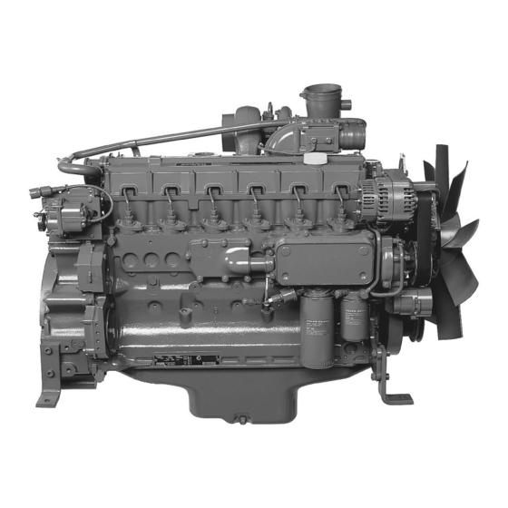
Presentation TD420VE, TAD420VE, TD520GE, TAD520GE and TAD520VE are in-line, direct injected, 4-cylinder industrial diesel engines. TAD620VE, TD720GE, TAD720GE, TAD720VE, TAD721GE, TAD721VE, TAD722GE and TAD722VE are in-line, direct injected, 6-cylinder industrial diesel engines. All engines are equipped with electronically controlled fuel management (EDC4), turbocharger, thermostatically controlled cooling systems and electronic speed control. - Page 11 Presentation TD420VE, TAD420VE, TAD620VE TD520GE, TAD520GE, TAD520VE TD720GE, TAD720GE TAD720VE, TAD721GE, TAD721VE, TAD722GETAD722VE...
-
Page 12: Identification Numbers
Presentation Identification numbers Location of engine signs The engines are supplied with two engine signs, of which one is installed on the right side of the engine block. Engine plate 1. Engine model 9. Air temperature in °C (°F), in accordance with 2. -
Page 13: Edc 4
Fault codes can also be output via the – speed sensor, camshaft CAN interface or with Volvo’s VODIA tool (including the Penta EDC4 software) at an authorized Volvo – coolant temperature sensor Penta workshop. -
Page 14: Instruments
Instruments The engines are not supplied with instruments and controls. The choice of instrument type and controls is made by the customer. The functions available are described below. A. Engine speed potentiometer (throttle control) B. CAN interface SAE J 1939 C. -
Page 15: Starting The Engine
Starting the engine Make it a habit to check the engine and engine room before starting. This will help you to discover quickly if anything abnormal has happened, or is about to happen. Also check that instruments show normal values after starting. -
Page 16: Starting In Extreme Cold
Pre-heat the coolant with a separately installed elec- tric engine heater. In extreme cases, a diesel-burning engine heater may be needed. Ask your Volvo Penta dealer for advice. IMPORTANT! Make sure that the cooling sys- tem is filled with a glycol mixture. Please refer to the “Maintenance, cooling system”... -
Page 17: Never Use Start Spray
Starting the engine Never use start spray WARNING! Never use start spray or similar products as a starting aid. Explosions could oc- cur in the inlet manifold. The consequence could be personal injury. Starting with auxiliary batteries WARNING! Batteries (especially auxiliary bat- teries) contain hydrogen which is highly explo- sive in contact with air. -
Page 18: Operation
Operation Correct operation technique is very important for both fuel economy and engine life. Always let the engine warm up to normal operating temperature before operating at full power. Avoid sudden throttle openings and operation at high engine speeds. Checking instruments Engine speed control Check all instruments directly after starting, and then Avoid sudden and violent throttle opening. -
Page 19: Stopping The Engine
Stopping the engine During longer breaks in operation, the engine must be warmed up at least once every fortnight. This prevents corrosion damage in the engine. If you expect the engine to be unused for two months or more, it must be laid up: Please refer to the “Laying up”... -
Page 20: Maintenance Schedule
IMPORTANT! When both operation and calendar time are specified, do the mainte- nance job at the interval which is reached first. Maintenance points marked must be done by an authorized Volvo Penta workshop. Daily, before first start • Engine oil, level check ................ - Page 21 Maintenance schedule Every 50-600 hours or at least every 12 months • Engine oil and oil filter, change ............. page 22-23 Oil change intervals vary, depending on oil grade and sulfur content of the fuel. page 26. Every 500 hours •...
-
Page 22: Maintenance
8 hours. When operated in extremely dirty conditions, such as coal mines, stone crushing mills etc., special filters are needed (not sold by Volvo Penta). Air hoses. Leakage check. Inspect the condition of the hoses, for cracks and other damage. - Page 23 It should be possible to press the belts down about 10 mm (3/16 “) between the pulleys. Worn belts which operate in pairs should be changed together. On TD420VE, TAD420VE and TAD620VE, the fan belts have an automatic belt tensioner and do not need to be adjusted.
-
Page 24: Lubrication System
If the 6 and 7 liter engines are equipped with a low-profile oil pan, the oil change intervals should be changed. VDS = Volvo Drain Specification Global DHD = Global Diesel Heavy Duty ACEA = Association des Constructeurs Européenne d’Automobiles... - Page 25 Maintenance Viscosity Select the viscosity from the table below, for the ap- propriate continuous ambient air temperature. * Refers to synthetic or semi-synthetic oils. Oil change volume Please refer to the “Technical Data” chapter. Oil level. Inspection Make sure that the oil level is between the MAX and MIN marks.
-
Page 26: Cooling System
The coolant should contain ethylene glycol of a good quality with a suitable chemical consistency for an ade- quate protection of the engine. Using anti-corrosion aditive exclusively is not permitted in Volvo Penta’s engines. Never use water by itself as coolant. - Page 27 (18°F). (Using 60 % glycol lowers the freezing point to -54 °C (65°F)). Never mix more than 60 % concen- trate (Volvo Penta Coolant) in the cooling liquid, this will give reduced cooling effect and increase the risk of overheating, and will give reduced freezing protec- tion.
- Page 28 Maintenance Coolant. Checking and filling WARNING! Do not open the filler cap when the engine is warm, except in emergencies. Steam or hot fluid could spray out. Check the coolant level daily before starting. Top the coolant up as necessary. The level should be about 50 mm (2”) below the sealing plane of the filler cap, or between the MIN and MAX markings, if a separate expansion tank is installed.
- Page 29 Maintenance Coolant. Draining. The engine must be stopped before draining, and the filler cap unscrewed. WARNING! Do not open the filler cap when the engine is warm, except in emergencies. Steam or hot fluid could spray out. Open the drain taps and remove the drain plugs (po- sitions are shown below).
- Page 30 Maintenance Cooling system Flushing Cooling performance is reduced by deposits in the radiator and cooling galleries. The cooling system should be flushed when the coolant is changed. 1. Drain the coolant, as in the description on the pre- vious paragraph. 2.
-
Page 31: Fuel System
Maintenance Fuel system Only use the grades of fuel recommended in the fuel specification below. Always observe the greatest cleanli- ness during re-fueling and work on the fuel system. All work on the injection system of the engine must be done by an authorized workshop. If the seal on the in- jection pump is broken by an unauthorized person, all warranties are void. - Page 32 Maintenance Fuel system. Venting The fuel system must be vented after a filter change, if the fuel tank has been run dry, after a long-term stoppage etc. Use the hand pump, if fitted, to vent the fuel system. In other cases, vent the system by operating the starter motor.
-
Page 33: Electrical System
IMPORTANT! Never disconnect the current with the main switch when the engine is running. Electrical connections Check that electrical connections are dry, free from oxide and that they are securely tightened. Spray these connections as necessary with water-repellent spray (Volvo Penta universal oil). - Page 34 Maintenance Battery. Maintenance WARNING! Fire and explosion hazard. Batter- ies must never be exposed to open flames or sparks. WARNING! Never confuse the positive and negative poles on the batteries. Risk of arcing and explosion. WARNING! Battery electrolyte is highly corro- sive.
- Page 35 Maintenance Batteries, charging WARNING! Explosion risk! Hydrogen is given off when batteries are charged. This forms an explosive mixture with air. A short circuit, open flame or spark could cause a violent explosion. Ventilate well. WARNING! Battery electrolyte is highly corro- sive.
- Page 36 Maintenance Component location Speed sensor, camshaft Speed regulator / Actuator Coolant temperature sensor Charge pressure sensor, 3 pin* Charge pressure sensor, 4 pin* Connection to control unit Fuel temperature sensor Oil pressure sensor * Only one type of sensor is used.
-
Page 37: Laying Up
Before laying up for a long period of time, an authorized Volvo Penta workshop should check over the engine and other equipment. Have any faults and deficiencies attended to, so that the equipment is in order, ready for the next start. -
Page 38: Fault Tracing
A number of symptoms and possible causes of engine malfunctions are described in the table below. Always contact your Volvo Penta dealer if any problems occur which you can not solve by yourself. WARNING! Read through the safety advice for care and maintenance work in the “Safety information”... -
Page 39: Diagnostic Function
Diagnostic function The diagnostic function monitors and checks that the EDC 4 system functions normally. Diagnostic function Effect on engine The diagnostic function has the following tasks: The diagnostic function affects the engine in the fol- • lowing ways: Discover and localize malfunctions. •... - Page 40 Diagnostic function During operation The fault code consists of three groups of flashes, separated by a pause of two seconds. If the diagnostic lamp starts to flash during operation: The first and third group consist of short flashes (0.4 1. Reduce engine speed to idling. s).
-
Page 41: Fault Codes
Fault codes WARNING! Read through the safety advice for care and maintenance work in the “Safety information” chapter before starting work. Code 2.0.0 No faults There are no active faults. PID 91, Code 2.2.1 Accelerator pedal sensor Reason: Faulty sensor, connector or cable. Reaction: The engine goes into “limp home”... - Page 42 Fault codes PID 102, Code 2.2.3 Charge pressure sensor PID 174, Code 2.2.7 Fuel temperature sensor Reason: Faulty sensor, connector or cable. Reason: Faulty sensor, connector or cable. Reaction: A fault code is generated. Reaction: A fault code is generated. Action: Action: •...
- Page 43 Fault codes PID 111, Code 2.3.5 Warning, coolant level PID 174, Code 2.3.7 Warning, fuel temperature Reason: Coolant level too low Reason: Excessive fuel temperature. Reaction: A fault code is generated. Reaction: A fault code is generated. The fault code disappears when the fuel temperature falls below the Action: recuperation value.
- Page 44 Fault codes PID 111, Code 2.3.5 Emergency stop, coolant SID 23, Code 2.5.1 Control rod position sensor, level difference Reason: Low coolant level Reason: Injection pump/actuator has got stuck or is not connected. Difference between control rod cur- Reaction: The engine is emergency stopped and rent value and nominal value exceeds 10%.
- Page 45 Fault codes SID 252, Code 2.8.1 Parameter programming PID 158, Code 2.8.2 Reference voltage 2 Reason: Memory fault Reason: Reference voltage for actuator exceeds per- missible limit values. Reaction: The engine is emergency stopped and Reaction: A fault code is generated. The fault code can not be re-started until the fault is rectified.
- Page 46 Felkoder PID 48, Code 2.9.2 Atmospheric pressure Reason: Air pressure is outside permissible values. Reaction: A fault code is generated. The fault code disappears when the pressure returns to normal. Monitoring function for air pressure is activated. Action: • Turn the ignition off and on, and check if the fault code remains.
-
Page 47: Technical Data
Technical data General Type designation ..........TD420VE TAD420VE TAD620VE Direction of rotation (seen from flywheel) ....Anti- clockwise Anti- clockwise Anti- clockwise No. of cylinders ............4 Cylinder bore mm (inch) ........101 (3.97”) 101 (3.97”) 98 (3.86”) Stroke mm (inch) ..........126 (4.96”) 126 (4.96”) - Page 48 Technical data Type designation ......TAD720VE TAD721VE TAD722VE Direction of rotation, seen from flywheel: Anti- clockwise Anti- clockwise Anti- clockwise No. of cylinders ......Cylinder bore mm (inch) ....108 (4.25”) 108 (4.25”) 108 (4.25”) Stroke mm (inch) ......130 (5.12”) 130 (5.12”) 130 (5.12”) Cylinder volume liter (inch...
- Page 49 Technical data Type designation ......TAD721GE TAD722GE Direction of rotation, seen from flywheel: Anti- clockwise Anti- clockwise No. of cylinders ......Cylinder bore mm (inch) ....108 (4.25”) 108 (4.25”) Stroke mm (inch) ......130 (5.12”) 130 (5.12”) Cylinder volume liter (inch ) ..
-
Page 50: Lubrication System
Technical data Lubrication system Change volume, including filter change, TD420VE/TAD420VE:..........10 liter (2.64 US gal) TD520GE/TAD520GE/TAD520VE: ......13 liter (3.43 US gal) TAD620VE: ............. 16 liter (4.22 US gal) TAD720VE/TAD721VE/TD720GE/TAD720GE: ..20 liter (5.28 US gal) TAD722VE: ............. 23 liter (6.07 US gal) TAD721GE/TAD722GE: ........... -
Page 51: Fuel System
Technical data Fuel system Injection sequence TD420VE/TAD420VE/TD520GE/ TAD520GE/TAD520VE: ........... 1-3-4-2 TAD620VE/TD720GE/TAD720GE/ TAD720VE/TAD721VE/ TAD722VE TAD722GE/TAD722VE: .......... 1-5-3-6-2-4 Feed pump Supply pressure: ............0.5 MPa (72.5 psi) Supply pressure after fuel filter at 1500 rpm: Min ............0.28 MPa (40.6 psi) By-pass valve Opening pressure ............ -
Page 52: Cooling System
Technical data Cooling system Type ................Pressurized, sealed Pressure cap, max. opening pressure: TD420VE/TAD420VE/TAD620VE/ TD520GE/TAD520GE/ TAD520VE/TAD720VE/TAD721GE TAD721VE/TAD722GE/TAD722VE: ......90 kPa (13 psi) TD720GE/TAD720GE: ..........60 kPa (8.7 psi) Refers to VE engines which are not equipped with a pressure valve at the factory. - Page 53 Notes ..............................................................................................................................................................................................................................................................................................................................................................................................................................................................................................................................................................................................................................................................................................................................................................................................................................................................................................................................................................................................................
- Page 54 Notes ..............................................................................................................................................................................................................................................................................................................................................................................................................................................................................................................................................................................................................................................................................................................................................................................................................................................................................................................................................................................................................
- Page 55 Notes ..............................................................................................................................................................................................................................................................................................................................................................................................................................................................................................................................................................................................................................................................................................................................................................................................................................................................................................................................................................................................................
- Page 56 ✂ Yes please, I would like an operator’s manual in English at no charge. Publication number: 7745202 Post or fax this coupon to: Document & Distribution Center Name Order Department ARU 2, Dept. 64620 Address SE-405 08 Göteborg Sweden Fax: +46 31 545 772 Orders can also be placed via the Internet: http://www.volvopenta.com/...
- Page 57 ✂ Sí gracias, deseo recibir gratuitamente un libro de instrucciones en español. Número de publicación: 7745205 Franquear o enviar fax a: Document & Distribution Center Nombre Order Department ARU 2, Dept. 64620 Dirección SE-405 08 Göteborg Suecia Fax: +46 31 545 772 El pedido puede hacerse tam- bién por internet: http://www.volvopenta.com/...
- Page 58 ✂ Ja graag, Ik wil kosteloos een instructieboek in het Nederlands ontvangen. Publicatienummer: 7745208 Stuur of fax de coupon naar: Document & Distribution Center Naam Order Department ARU 2, Dept. 64620 Adres SE-405 08 Göteborg Zweden Fax: +46 31 545 772 U kunt ook bestellen via internet: http://www.volvopenta.com/...
- Page 59 ✂ Íáé, Èá Þèåëá Ýíá áíôßôõðï ôïõ åã÷åéñéäßïõ ÷ñÞóçò óôçí áããëéêÞ ãëþóóá ÷ùñßò êáìéÜ ÷ñÝùóç. Áñéèìüò Ýêäïóçò: 7745210 Ôá÷õäñïìÞóôå áõôü ôï ¼íïìá êïõðüíé óôçí ðáñáêÜôù äéåýèõíóç Þ óôåßëôå ôï ìå öáî óôïí ðáñáêÜôù áñéèìü Äéåýèõíóç öáî: Document & Distribution Center Order Department ARU 2, Dept.
Need help?
Do you have a question about the TD420VE and is the answer not in the manual?
Questions and answers