Advertisement
Quick Links
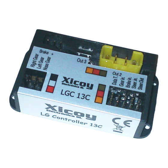
Electric Landing Gear controller and sequencer
LGC 13C
Users Guide.
Torrent d'en Puig, 31. 08358, Arenys de Munt, Barcelona,Catalonia,Spain
E-mail: info@xicoy.com. Fax: +34 933 969 743 web:
www.xicoy.com
© Copyright 2013, Xicoy Electronica SL. All Rights Reserved
Manual contents & design: Gaspar Espiell
Advertisement

Related Manuals for XICOY LGC 13C

Summary of Contents for XICOY LGC 13C
- Page 1 Electric Landing Gear controller and sequencer LGC 13C Users Guide. Torrent d’en Puig, 31. 08358, Arenys de Munt, Barcelona,Catalonia,Spain E-mail: info@xicoy.com. Fax: +34 933 969 743 web: www.xicoy.com © Copyright 2013, Xicoy Electronica SL. All Rights Reserved Manual contents & design: Gaspar Espiell...
-
Page 2: Electrical Connections
Welcome! Congratulations on the purchase of your new landing gear controller. Xicoy are dedicated to the design and production of electronic controllers to the highest standards of quality and reliability to bring you the customer the very latest next generation designs. -
Page 3: Please Read
lead to correct output in order that later during programming, the delays are applied to correct retract. The polarity of the connection lead is marked on the label of the unit. In the case of using reversed gears, the connector should be connected backwards to reverse the operation of the motors. - Page 4 Always fully disconnect the batteries (both poles) from the installation before charging, as current can flow trough the unit from one battery to the other during charge, damaging the installation. Please contact to Xicoy Electronica for advice on particular installations.
- Page 5 The following setup procedure assumes the use of a Xicoy data terminal, please jump to the “Manual Setup” section for the pushbutton and Led setup procedure. Setup using a data terminal: Connect the data terminal (Same model as used by Xicoy V10 ecus) on the socket at Gear In left side of input.
- Page 6 Radio Setup: On this section you can program the radio inputs to mach your transmitter and setup the brake power. First screen is the Gear Up position: Set the transmitter switch or slider of the gear channel in the position you wish that the gear be in retracted position.
- Page 7 It is possible to define 3 different positions for each output: Gear Up position: The position you wish that the servo be driven when the gear is retracted. Typically is a closed door. Gear Down position: The position you wish that the servo be driven when the gear is extended.
- Page 8 switch off feature, check first if your servo is compatible, or use a analog servo. The Hitech and Multiplex digital servos we have tested are not suitable, but JR 8511 is. Motor delay: To replicate the operation of full size landing gears, it is possible to set a programmable delay for each motor operation.
- Page 9 possible that the centering need a new adjust, just go back to previous adjustment by the menu buttons. Motor adjust: This last section of adjustment allows adapting the unit to different motors. These adjustments are not available in some of the units that are setup by motor manufacturer.
- Page 10 Setup without the Data terminal: There is a LED indicator and a pushbutton to allow setup the unit without the data terminal. In this case the options are considerably reduced from the full options available using the data terminal. Connect the RC channels you want to use (Gear In obligatory, Brake In and Steering In optional).
Need help?
Do you have a question about the LGC 13C and is the answer not in the manual?
Questions and answers