Table of Contents
Advertisement
Advertisement
Table of Contents

Subscribe to Our Youtube Channel
Related Manuals for XICOY FADEC system Autostart 10

Summary of Contents for XICOY FADEC system Autostart 10
- Page 1 FADEC system - Autostart 10 Users Guide. Torrent d’en Puig, 31. 08358, Arenys de Munt, Barcelona,Spain E-mail: info@xicoy.com. Fax: +34 933 969 743 web: www.xicoy.com © Copyright 2010, Xicoy Electronica SL. All Rights Reserved Manual contents & design: Gaspar Espiell...
- Page 2 Damage or defective operation covered under the warranty terms will be repaired and tested at no cost the original owner (other than postage and packaging). Repairs not covered under the terms of warranty will be carried out by Xicoy Electronica SL, or their appointed agents after agreement of costs.
- Page 3 Start modes: Manual, Auto Gas and Kerostart (1) • (1) Currently Xicoy Electronica offer 2 models of Fadec 10, one that allow manual and gas start, and the second, that allow manual, gas and kerostart. In this manual all the comments about kerostart apply only to Kerostart...
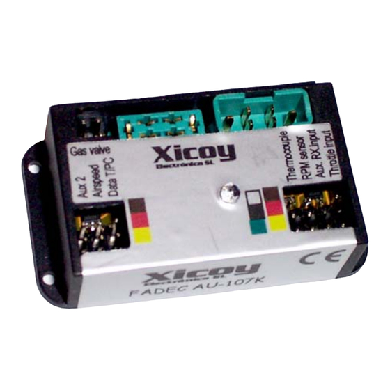
- Page 4 Connections: The FADEC have 3 types of connections: Power connections: Two high quality MPX connectors carry all the power current. Each power lead is identified by the label on the FADEC body. The female MPX plug provides the power to the glow plug and starter motor.
- Page 5 Connect the RPM sensor and thermocouple on its respective sockets, in the orientation that is shown in the colored labels on the fadec. If necessary, both leads can be extended using good quality servo extensions. Connect the throttle lead from the RX in its place, in the upper position.
- Page 6 Using and Programming the FADEC: All the programming and measures are done trough the data terminal. Once the FADEC is programmed, it is not necessary its use and it is not recommendable to leave it inside the airplane to minimize the risk of interferences. The data terminal has a 16 character LCD screen and 4 buttons.
- Page 7 Aligning the transmitter with the FADEC Turn on the transmitter and receiver. Using the “menu up” and (-) buttons move to the “Radio” menus. First screen will be this one: If you are sure that you want to modify the radio settings then press the right hand button (+) and the screen will change to: On your transmitter, raise first the...
- Page 8 On rare occasions, usually when using a Futaba transmitter, it has been found that the throttle channel sense of movement may require reversing (Servo reverse) and repeat the transmitter alignment. Correct reading of throttle % by the FADEC can be verified in the second screen, percentage of the throttle position is shown on, 0% in the position of engine stop (trim and stick down), 100% with stick/trim full up and between 10% and 30% at idle.
- Page 9 The total running time of the engine in minutes (Tot), The time in seconds of the last engine run (Last) The total number of starts (cycles - CY). Use this screen to keep track of your total running time and starts. Battery used Counter.
- Page 10 the fadec only can reduce the throttle, it never will give more power than the one set by the pilot trough the throttle command. Second screen show the maximum airspeed reached on last flight in mph and km/h. This maximum is set to zero on next engine start. Setting the throttle to higher than 50% (with engine off) the second line will change to “Current airspeed”...
- Page 11 engine running the fadec will adjust the rotor speed accordingly the throttle position in a closed loop system. STOP speed: Set the minimum RPM that the engine is allowed to run. The FADEC will shutdown the engine if the rotor speed is below this setting. Start/Min temperature: minimum...
- Page 12 START menus: On this submenu you will find the parameters used during the engine startup. Like the “RUN” menus, some of these parameters could be not available in fadecs used in production engines. There are 3 start modes available: -Manual, where the user should do all the start sequence, and the fadec only control the pump and the fuel valve -AUTO-Gas: The fadec do all the start sequence automatically controlling the starter,...
- Page 13 Manual mode: From values from 9 to 255 the power applied to the pump is fixed. It is necessary to test with the selected pump and battery the right value to have the pump to start at the desired speed. Pump Start ramp: This parameter adjust the speed of the fuel increase during the “Fuel ramp”...
- Page 14 2. When "Ready" is displayed, the user should cycle the stick to full power and back to idle. 3. When the stick is at idle again, the start sequence begins. 4. The glow-plug is powered and checked. Once hot, the starter is engaged at reduced power (soft start) and the gas valve is energized.
- Page 15 Low Batt. Volts: During on start phase the fadec check the battery voltage, and abort the start if the voltage falls below this setting. Once the engine is running, the FADEC ignore this voltage and keep the engine running until the battery is fully depleted.
- Page 16 2009 with hundreds of engines sold. It is a proven system, but this doesn’t guarantee a success in your particular engine. The support from Xicoy Electronica will be limited to the present user's • manual and clarifications to it. We will not supply turnkey systems, parameter list, etc, because it is impossible for us to test and know all the engines and engine variants in the market.
- Page 17 problem, like a disconnected burner or an overload, the sequence will be aborted and a error message will be displayed. 3) Once the burner is at temperature, the starter is powered. First 2s the power is set fixed by the parameter "Starter power at ignition" to assure a good bendix engagement. After these 2 seconds, the starter power is regulated automatically to have the rotor turning at the RPM set by "Rpm at ignition".
- Page 18 ” RPM Fuel Ramp K” . Set the rotor RPM where the fuel will be feed only to main injectors only and the burner switched off. Typical values 6.000-12.000 RPM ” Pump Start point” Set the start power of the pump. Exactly same as gas start. ”Glow plug power”...
- Page 19 During engine operation the FADEC measures and stores all the engine operating parameters recorded during the last the 51 minutes of operation. These measures can be downloaded later to a PC to study the behavior of the engine in flight and to diagnose any possible problems.
- Page 20 The user must provide an emergency shut-off (i.e. a servo operated cut-off valve) for increased security. Please read and follow the GTBA code of practice. (http://www.gtba.co.uk/codes/index.htm)
Need help?
Do you have a question about the FADEC system Autostart 10 and is the answer not in the manual?
Questions and answers
what is the difference between a fadec au 107k and a fadec au 108k ?