VENCO VHR Series Installation, Operation, & Maintenance Instruction
Heat pump heat recovery units
Hide thumbs
Also See for VHR Series:
- Quick start manual (4 pages) ,
- Installation, operation, & maintenance instruction (31 pages)
Table of Contents
Advertisement
Advertisement
Table of Contents

Related Manuals for VENCO VHR Series


Summary of Contents for VENCO VHR Series
- Page 1 INSTALLATION – OPERATION & MAINTENANCE INSTRUCTION HEAT PUMP HEAT RECOVERY UNITS VHR MODELS VENCO Havalandırma ve Makina San.ve Tic. A.Ş. 2004. Cad. No:5 45400 OSB Turgutlu – MANISA / TURKEY Tel: 0 (236) 332 5070 Fax: 0 (236) 332 5030 www.venco.com.tr venco@venco.com.tr...
-
Page 2: Table Of Contents
INTRODUCTION ........................... 3 HEAT RECOVERY UNITS and VHR MODELS ..................3 Figure 2.1.1 VENCO VHR DX HEAT PUMP HEAT RECOVERY UNIT ............. 3 Figure 2.2.1 Heat Pump Heat Recovery Units Parts ................. 4 TECHNICAL SPECIFICATION for HEAT RECOVERY UNITS .............. 5 Table 3.1. - Page 3 Figure 7.2.9. Access door label ....................... 13 Figure 7.2.10. Filter Access door label ....................13 Figure 7.2.11. Drain label ........................13 Figure 7.2.12. Fresh Air label ........................13 Figure 7.2.13. Exhaust air label ....................... 13 CONTROLS BEFORE START UP ...................... 13 8.1.
-
Page 4: Introduction
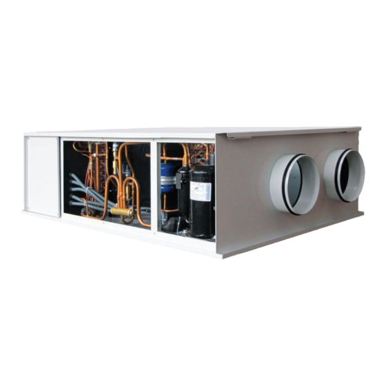
2. HEAT RECOVERY UNITS and VHR MODELS VENCO Heat Recovery Units are classified 8 different models; VHR 05 DX – 07 DX – 10 DX – 15 DX - DX – 21 DX – 30 DX – 40 DX (Figure 2.1.). In all models, the housing is made from epoxy coated galvanized sheet metal and the cabinet is fully insulated for sound and heat isolation. - Page 5 Heat Pump Heat Recovery Units as standard consist of seven different parts as described; These parts Exhaust Fan, Supply Fan, Fresh Air Filter, Exhaust Air Filter, Plate Type Heat Exchanger, Exhaust Coil and Fresh Air Coil part, Compressor and Electrical Connection Box. Exhaust Air Fresh Air Filter and...
-
Page 6: Technical Specification For Heat Recovery Units
3. TECHNICAL SPECIFICATION for HEAT RECOVERY UNITS Technical specifications, which are valid for the heat pump heat recovery units are given in the table below. Table 3.1. VHR DX Heat Pump Heat Recovery Unit Technical Specifications VHR 05 VHR 07 VHR 10 VHR 15 VHR 20... - Page 7 Table 3.2. Dimensions for VHR DX Heat Pump Heat Recovery Unit VHR 05 VHR 07 VHR 10 VHR 15 VHR 20 VHR 21 VHR 30 VHR 40 VENCO MODEL Length [mm] 1140 1315 1350 1615 1810 1910 2000 2000 Width [mm]...
-
Page 8: Working Conditions
5.2 Storage VENCO heat recovery units have to be kept in a closed area where the heat should be between – 20 ºC and + 40 ºC and relative humidity should not exceed 80%. Also the unit should be kept away from dust, gas, corrosive streams and effects causing corrosion. -
Page 9: Installation
5.3 Installation VENCO rules should be implemented during the final assembly. Before the installing of heat recovery units, customers should control whether weight and dimensions of the stations are suitable for the places from where stations will pass through and assembly will be carried out. The unit has to be install horizontally, any angle installation will cause a problem. - Page 10 Fan service Filter service cover(Model 1) cover Fan service Filter service cover (Model 2) cover Figure 5.3.3. Installation Schema 2016.09 9 / 28...
-
Page 11: Connections
6. CONNECTIONS 6.1. Duct Connections Return air, fresh air, exhaust air and supply air ducts should be fixed (connected) to the unit with flexible connection. Required leak-proofing should be obtained in order to ensure desirable air flow. Having improper (bad) unit – duct connections and wrong dimension, shape and duct fragments inside of the connection may cause turbulence. -
Page 12: Drain Connections
Figure 6.1.4. Unit Outlets when the air flow direction change 6.2. Drain Connections The diameter of drain pipe should be equal the diameter of drain pipe on the unit. Drainage pipe and drain pan connections should be made by ripple and flange to be able to dismantle pipe connections easily in order to clean up the residue occurred on drain pan and pipes. -
Page 13: Safety Requirements
inside insulation has to be done immediately if any damage occurs. The particles have to be removed if there is any inside the unit. These kind of products cause corrosion especially in the high humidity conditions. For unit electrical connections, put the safety fuse to the main supply board.(for capacity list , go to document APPENDIX-4 ) All the electrical connections have to be appropriate to given document APPENDIX-4. -
Page 14: Controls Before Start Up
Please check the inside of product, are there any particles which can damage the unit. Please check both inside and outside of product are there any damages were happened because of mechanical reasons. If yes, please note the main reason and apply the precautions not to go wider. If necessary please contact with VENCO. 8.2. Filters 2016.09... -
Page 15: Heat Recovery Exchanger
Maintenance of the filters should be done regularly. Dirty filters can decrease air flow and consequently the capacity. Synthetic or metal filters can be cleaned or washed. However it is advised to change synthetic filters every two years. 8.3. Heat Recovery Exchanger Is controlled before transportation. -
Page 16: Safety Warnings
9. SAFETY WARNINGS VENCO heat pump heat recovery units are produced in accordance with EN 60204-1 standards and to fulfill the requirements MD 98/37 of the European Directives. The products have CE mark. This user manual is prepared to provide correct usage and assembling of the heat recovery unit and warn the maintenance personnel for the possible dangers they may occur. -
Page 17: Warning Signs
Maintenance For the continuity of the warranty, control and maintenance responsibilities have to be accepted and followed strictly. You can apply to VENCO A.S. to train your authorized technicians. 9.4. General Hazards Prevention Heat recovery units service cover is screwed to the unit. Thus, with the danger of unauthorized persons are prevented to reach inside the unit. -
Page 18: Start-Up And Operating
10. START-UP AND OPERATING 10.1. Commissioning Instructions have to be followed before operating the unit for the first time (or after yearly maintenance). Additionally, following checks have to be done. Please make sure that all parts of the unit are clean. There can be duct insulation residuals, bands etc. ... - Page 19 Check whether any changes at the fan. A more detailed explanation of the problems and the possible causes of these problems is given in "troubleshooting" section. For questions about the changes during periodic observations, you can contact VENCO or other competent adviser. Make the fan stop until to fix if any vibration appears at fan.
-
Page 20: Electronic Controller Board
11. ELECTRONIC CONTROLLER BOARD 11.1. DX Controller VENCO DX heat recovery device used to control the fresh air fan FAN1 (5 step+auto), the exhaust air fan FAN2 (5 step+auto), the selection of mode (heating cooling, fan and auto). İnformation on the control keys are given in the following template. - Page 21 Using the mode button, you can make the mode (Heat, cool, fan and auto) selection. If the fan button is pressed, makes of the fresh air fan speed control (1 / 2 / 3 / 4 / 5-automatic). When the fan button is second pressed, makes of the exhaust fan speed control (1 / 2 / 3 / 4 / 5-automatic).
-
Page 22: Maintenance
12. MAINTENANCE Before all the periodic maintenance, the device is switched off and wait at least two minutes for the fan stop working completely. Drain Outlet once in 3 months, please check water flow from drain pipe. Air Filters; once in 3 months, please check the filters. Please wash it or change it when necessary. Otherwise ventilation will inefficient and energy consumption will raise. - Page 23 2016.09 22 / 28...
- Page 24 13.1. Diagnosing and Fixing Table INDICATIONS POSSIBLE REASON OTHER RESONS and REMEDIES PROBLEMS No power Check the power supply NO AIR The cables are defected which contacts No current FLOW motor Thermal protection is open Contactors or terminal are not tight Motor is not working Check the controller cable and behind...
-
Page 25: Service
After Sales Service VENCO heat recovery units does not require any replacement or repair beyond the control eye control and cleaning done by the user. Users must contact with VENCO for the faults. They identify during the maintenance or commissioning operation. -
Page 26: Appendix
15. APPENDIX 15.1. DHR DX 3.0 Electrical Wiring Diagram (5-7-10-15-20-21-30 DX) 2016.09 25 / 28... -
Page 27: Dhr Dx 3.0 Electrical Wiring Diagram (40 Dx)
15.2. DHR DX 3.0 Electrical Wiring Diagram (40 DX) 2016.09 26 / 28... -
Page 28: Dhr Dx 3.1 Pro Electrical Wiring Diagram (40 Dx)
15.3. DHR DX 3.1 PRO Electrical Wiring Diagram (40 DX) 2016.09 27 / 28... -
Page 29: Fuse And Wiring Selection
Fuse and wiring selection Fuse MODEL ELECTRIC POWER VOLTAGE - HZ FUSES 230 volt – 50 Hz VHR 05 DX 1290W 230 volt – 50 Hz VHR 07 DX 1350W 230 volt – 50 Hz VHR 10 DX 2020W 230 volt – 50 Hz VHR 15 DX 3270W 230 volt –...
Need help?
Do you have a question about the VHR Series and is the answer not in the manual?
Questions and answers