VENCO VHR Series Installation, Operation, & Maintenance Instruction
Hide thumbs
Also See for VHR Series:
- Quick start manual (4 pages) ,
- Installation, operation, & maintenance instruction (29 pages)
Table of Contents
Advertisement
Advertisement
Table of Contents

Related Manuals for VENCO VHR Series


Summary of Contents for VENCO VHR Series
- Page 1 INSTALLATION – OPERATION & MAINTENANCE INSTRUCTION HEAT RECOVERY UNITS VHR AND VHR EC MODELS VENCO Havalandırma ve Makina San.ve Tic. A.Ş. 2004. Cad. No:5 45400 OSB Turgutlu – MANISA / TURKİYE Tel: +90 (236) 332 5070 Fax: +90 (236) 332 5030 www.venco.com.tr venco@venco.com.tr...
-
Page 2: Table Of Contents
Index INTRODUCTION ............................. 4 HEAT RECOVERY UNITS and VHR MODELS ..................4 Figure 2.1. VENCO Heat Recovery Units ....................4 Figure 2.2. Heat Recovery Unit Schema ..................... 5 Figure 2.3. Heat Recovery Unit Schema (Plug) ................... 5 TECHNICAL SPECIFICATION for HEAT RECOVERY UNITS ..............6 Table 3.1.1 Technical Specifications for VHR Models ................. - Page 3 Image 14.2.1. Electronic Controller Buttons ....................19 TROUBLESHOOTING ........................21 Table15.1. Troubleshooting Table ......................21 SPARE PART LİST..........................21 Figure 16.1. Heat Recovery Spare Parts ....................22 APPENDIX ............................23 17.1. APPENDIX-1 Standard Controller (SEC) Electrical Wiring Diagram ..........23 17.2.
-
Page 4: Introduction
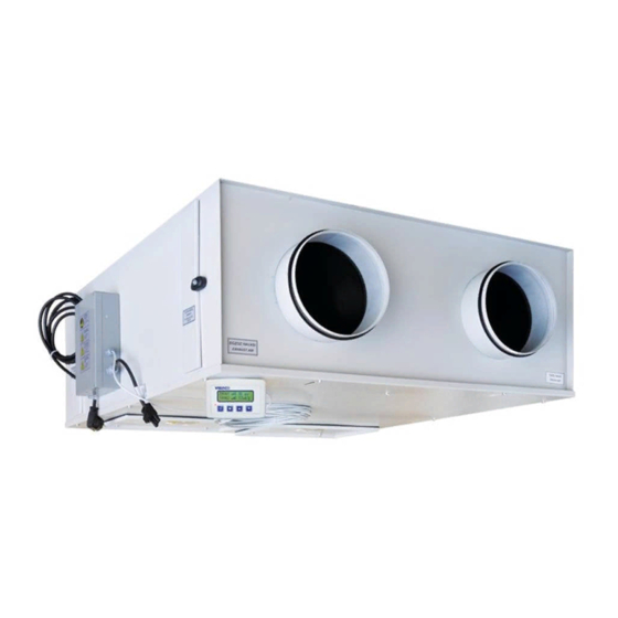
2. HEAT RECOVERY UNITS and VHR MODELS VENCO Standard Heat Recovery Devices are classified in 10 different models; VHR 04 - 07 - 09 - 11 - 16 - 20 - 23 - 29 - 36 - 51. High efficiency EC fan devices are classified in 7 different models; VHR 04 EC - 09 EC - 11 EC - 16 EC - 29 EC - 36 EC - 51 EC. - Page 5 Heat Recovery units as standard consist of five different parts as described; Exhaust Fan, Supply Fan, Fresh Air Filter, Exhaust Air Filter, Plate Type Heat Recovery Exchanger. Drain Pan Fresh Air Fan, Direct Exhaust Air Fan, Direct Driven Driven Heat Recovery Plate Filter Exchanger Filter...
-
Page 6: Technical Specification For Heat Recovery Units
3. TECHNICAL SPECIFICATION for HEAT RECOVERY UNITS Technical specifications, which are valid for the heat recovery units as standard manufactured by VENCO, are given in the table below. Table 3.1.1 Technical Specifications for VHR Models MODEL m³/h Air Flow 0 Pa*... - Page 7 Table 3.1.2 Technical Specifications for VHR EC Models MODEL 04 EC 09 EC 11 EC 16 EC 29 EC 36 EC 51 EC m³/h Air Flow 0 Pa* 1252 1468 2261 2858 3810 4993 m³/h Air Flow 150 Pa* 1091 1058 2112 2657...
- Page 8 Table 3.2. Dimensions for VHR and VHR EC Models 2019.10 8 / 31...
- Page 9 MODEL VHR 04 VHR 07 VHR 09 VHR 11 VHR 16 VHR 20 VHR 23 VHR 29 VHR 36 VHR 51 Length [mm] 1115 1125 1125 1.400 1.450 1.650 Width [mm] 1020 1030 1.100 1160 Height [mm] Duct Connection Ød Ø160 Ø200 Ø200...
-
Page 10: Working Conditions
If there is no frost protection on the unit and the outside temperature is less than -5°C, the unit must be stopped and you should contact with VENCO. The condense water can be frozen at the temperature less than -5°C and it can damage the exchanger. - Page 11 Electrical Connection Filter Service Doors Service Door Figure 5.2. Installation Schema INDOOR Fresh Air OUTDOOR Exhaust Air OUTDOOR INDOOR Fresh Air Exhaust Air Model min. [mm] Service Zone VHR 04/04EC VHR 07 Figure 5.3. Connection Schema (Top View) VHR 09/09EC VHR 11/11EC VHR 16/16EC VR 20...
-
Page 12: Connections
INSIDE Electrical Duct Fresh Air Heater Connection Duct L = 2 D INSIDE Exhaust Air OUTSIDE Exhaust Air OUTSIDE Fresh Air Figure 5.4 Connection Schema 6. CONNECTIONS 6.1. DUCT CONNECTIONS Return air, fresh air, exhaust air and supply air ducts should be fixed (connected) to the unit with flexible connection. -
Page 13: Drain Connections
Appendix 1. 7. SAFETY REQUIREMENTS VENCO heat recovery units are produced according to EN 60204-1 Standards and MD 98/37 EC numbered European Union Directives and carry the CE signs on themselves. However, the unit can be dangerous if the unit is not used or the service is given by trained and experienced technicians, and indicated security 2019.10... -
Page 14: Safety Labels
Never expose fans, cables and connections to the water. If the outside temperature is less than -5°C, the unit must be stopped and you should contact with VENCO. The condense water can be frozen at the temperature less than -5°C, it can be damaged to the exchanger. -
Page 15: Controls Before Start-Up
Please make sure that all parts of the unit are clean. There can be duct insulation residuals, bands etc. If the outside temperature is less than -5°C, the unit must be stopped and you should contact with VENCO. The condense water can be frozen at the temperature less than -5°C, it can be damaged to the exchanger. -
Page 16: Training Of Technicians
Maintenance For the continuity of the warranty, control and maintenance responsibilities have to be accepted and followed strictly. You can apply to VENCO A.S. to train your authorized technicians. 11. RECOMMENDATIONS FOR SAFETY This user manual is prepared to provide correct usage and assembling of the heat recovery unit and warn the maintenance personnel for the possible dangers they may face. -
Page 17: Control Functions
14. CONTROL FUNCTIONS 14.1. Standard Electronic Controller (SEC) Figure 14.1.1. Standard Electronic Controller (SEC) VENCO VHR type heat recovery unit control functions are; Unit ON / OFF FAN 1 ( Supply fan ) Speed control as 5 steps and automatic ... - Page 18 Table 14.1.1. Electronic Controller Buttons Buttons Name Description ON / OFF Unit will be ON or OFF. Select Running Status MODE (Cool , Heat or Ventilation Increase, decrease selected fan’s stage value. Increase of set value. Increases the value of selected by Value Increase fan button area.
-
Page 19: Functional Electronic Controller (Fec)
Optionally, there is a control of air quality. The fan in AUTO (FAN1, FAN2 or BOTH) changes fan speed according to the information from sensors. 14.2. Functional Electronic Controller (FEC) VENCO VHR type heat recovery unit control functions are; Unit ON / OFF ... - Page 20 Decreases of the set value. Value Decrease Decreases the value of selected by fan button area. Icons Description Heater and cooler step (ST 1 - ST 1+2) Failure reporting (AL 01 - AL02 - AL 03) Fresh air fan step (0-1-2-3-4-5-automatic) Exhaust fan step (0-1-2-3-4-5-automatic) Using the mode button, you can make the mode (Heat, cool and fan) selection.
-
Page 21: Troubleshooting
step for defrosting. After defrosting, the device will return to its normal run conditions. Under these circumstances ‘’AL 01’’ will be shown on screen. Commands from the front panel will not run. When the optional filter sensor detects dirty filters, ‘’AL 03’’ warning will be shown on screen. When this warning is shown, the device will work properly, however the warning will be shown until filters are cleaned. - Page 22 Electrical Connection Control Panel Filters Radial Fans Heat Exchanger Figure 16.1. Heat Recovery Spare Parts 2019.10 22 / 31...
-
Page 23: Appendix
17. APPENDIX 17.1. APPENDIX-1 Standard Controller (SEC) Electrical Wiring Diagram 2019.10 23 / 31... -
Page 24: Appendix-2 Functional Controller (Fec) Ac Fan Electrical Wiring Diagram
17.2. APPENDIX-2 Functional Controller (FEC) AC FAN Electrical Wiring Diagram 2019.10 24 / 31... -
Page 25: Appendix-3 Functional Controller (Fec) Ec Fan Electrical Wiring Diagram
17.3. APPENDIX-3 Functional Controller (FEC) EC FAN Electrical Wiring Diagram 2019.10 25 / 31... -
Page 26: Appendix-4 Functional Controller (Fx 3.1 Pro) Ac Fan Electrical Wiring Diagram
17.4. APPENDIX-4 Functional Controller (FX 3.1 PRO) AC FAN Electrical Wiring Diagram 2019.10 26 / 31... -
Page 27: Appendix-3 Functional Controller (Fx 3.1 Pro) Ec Fan Electrical Wiring Diagram
17.5. APPENDIX-3 Functional Controller (FX 3.1 PRO) EC FAN Electrical Wiring Diagram 2019.10 27 / 31... -
Page 28: Appendix-3 230V / 50Hz / 1 Phase Electrical Heater Wiring Diagram
17.6. APPENDIX-3 230V / 50Hz / 1 Phase Electrical Heater Wiring Diagram 17.7. APPENDIX-4 400V / 50Hz / 3 Phase Electrical Heater Wiring Diagram 2019.10 28 / 31... -
Page 29: Appendix-5 Electrical Cable And Fuse Selection Tables
17.8. APPENDIX-5 Electrical Cable And Fuse Selection Tables Table 17.8.1. Heat Recovery Unit Electrical Power Supply and Circuit Breaker Selection Table POWER MODEL ELECTRICAL CONNECTION CIRCUIT BREAKER* CONSUMPTION 230 volt – 50 Hz VHR 04 104 Watt 2 Ampere 230 volt – 50 Hz VHR 07 204 Watt 2 Ampere... - Page 30 Table 17.8.2. Heat Recovery Unit Electrical Power Supply Cable Cross Section Table Cross Section [mm²] MODEL Cable Length [m] VHR 04 VHR 07 VHR 09 VHR 11 VHR 16 VHR 20 VHR 23 VHR 29 VHR 36 VHR 51 Cross Section [mm²] MODEL Cable Length [m] VHR 04 EC...
- Page 31 Table 17.8.3. Duct Type Electrical Heater Power Supply and Circuit Breaker Selection Table POWER MODEL ELECTRICAL CONNECTION CIRCUIT BREAKER* CONSUMPTION 230 Volt – 50 Hz – 1Phase VHR 04 /04 EC 1 kW 6 Ampere 230 Volt – 50 Hz – 1 Phase VHR 07 2 kW 16 Ampere...
Need help?
Do you have a question about the VHR Series and is the answer not in the manual?
Questions and answers