Table of Contents
Advertisement
Quick Links
Advertisement
Table of Contents

Related Manuals for VENCO VHR ER 01


Summary of Contents for VENCO VHR ER 01
- Page 1 INSTALLATION – OPERATION & MAINTENANCE INSTRUCTION ENERGY RECOVERY UNITS VHR ER MODELS VENCO Havalandırma ve Makina San.ve Tic. A.Ş. 2004. Cad. No:5 45400 OSB Turgutlu – MANISA / TURKİYE Tel: +90 (236) 332 5070 Fax: +90 (236) 332 5030 www.venco.com.tr venco@venco.com.tr...
-
Page 2: Table Of Contents
Index INTRODUCTION ............................. 4 ENERGY RECOVERY UNITS and VHR ER MODELS ................4 Figure 2.1. VENCO Energy Recovery Units ....................5 Figure 2.2. Energy Recovery Unit Schema ....................5 Figure 2.3. Heat Recovery Unit Schema (Plug) ................... 5 TECHNICAL SPECIFICATION for ENERGY RECOVERY UNITS............5 Table 3.1. - Page 3 Table 14.2.2. Keypad ................Hata! Yer işareti tanımlanmamış. TROUBLESHOOTING ........................17 Table15.1. Troubleshooting Table ......................17 SPARE PART LIST..........................18 Figure 16.1. Heat Recovery Spare Parts ....................18 APPENDIX ............................19 17.1. APPENDIX-1 Standard Controller (SEC) Electrical Wiring Diagram ..........19 17.2.
-
Page 4: Introduction
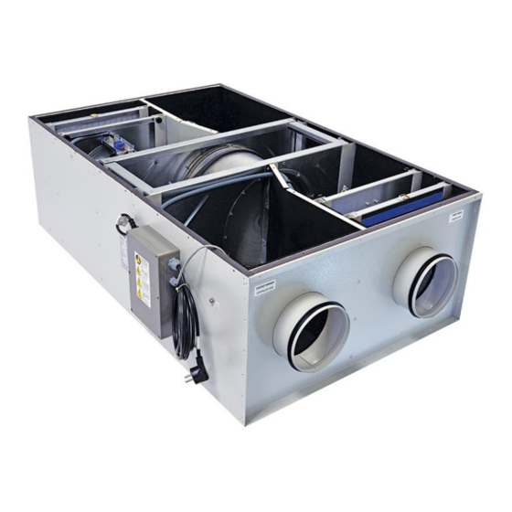
2. ENERGY RECOVERY UNITS and VHR ER MODELS VENCO Energy Recovery Units are classified 9 different models; VHR ER 01 – 04 – 06 – 08 – 15 – 28 – 35 – 40 – 51 – 54 (Figure 2.1). In all models, the housing is made from galvanized sheet metal and the cabinet is fully insulated for sound and heat isolation. -
Page 5: Technical Specification For Energy Recovery Units
Figure 2.2. VENCO Energy Recovery Units Schema 3. TECHNICAL SPECIFICATION for ENERGY RECOVERY UNITS Technical specifications, which are valid for the heat recovery units as standard manufactured by VENCO, are given in the table below. Table 3.1. Technical Specifications for VHR ER Models... - Page 6 VHR Energy Recovery Units are controlled with Standard Electronic Controller (SEC), supplied as standard with the unit. The supply air fan and return air fan are driven as 5 speeds with SEC. Also the electrical heater (optional) can be controlled by SEC manually or automatically depending on the room set temperature, has a protection system (optional) against the frost formation at the temperatures below -5°C, and Pressure Sensor (optional) for clogged filter.
-
Page 7: Working Conditions
If there is no frost protection on the unit and the outside temperature is less than -20°C, the unit must be stopped and you should contact with VENCO. The condense water can be frozen at the temperature less than -20°C and it can damage the exchanger. -
Page 8: Connections
6. CONNECTIONS 6.1. DUCT CONNECTIONS Return air, fresh air, exhaust air and supply air ducts should be fixed (connected) to the unit with flexible connection. Required leak-proofing should be obtained in order to ensure desirable air flow. Having improper (bad) unit – duct connections and wrong dimension, shape and duct fragments inside of the connection may cause a turbinated air flow. -
Page 9: Safety Requirements
Never expose fans, cables and connections to the water. If the outside temperature is less than -5°C, the unit must be stopped and you should contact with VENCO. The condense water can be frozen at the temperature less than -5°C, it can be damaged to the exchanger. -
Page 10: Controls Before Start-Up
Figure 8.2. Electrical warning Figure 8.3. Temperature Figure 8.1. Manuel label label warning label Figure 8.5. Wiring diagram label Figure 8.4. Repair warning label Figure 8.6.Ground label Figure 8.7. Fan label Figure 8.8.Electrical warning label Figure 8.9. Access door label Figure 8.10. -
Page 11: Training Of Technicians
If the outside temperature is less than -5°C, the unit must be stopped and you should contact with VENCO. The condense water can be frozen at the temperature less than -5°C, it can be damaged to the exchanger. Following points have to be controlled periodically. -
Page 12: Maintenance
Please take out filters after the first operation and clean them properly. Then insert the filters in it. If all access doors are taken out during the assembly, please make sure that service doors are closed. Control the adjustment of thermal over load relay. Give electricity and provide the fan to operate in the highest speed. -
Page 13: Control Functions
14. CONTROL FUNCTIONS 14.1. Standard Electronic Controller (SEC) Figure 14.1.1. Standard Electronic Controller (SEC) VENCO VHR type energy recovery unit control functions are; Unit ON / OFF FAN 1 ( Supply fan ) Speed control as 5 steps and automatic ... - Page 14 Using the mode button, you can make the mode (Heat, cool and fan) selection. If the fan button is pressed, makes of the fresh air fan speed control (1 / 2 / 3 / 4 / 5-automatic). When the fan button is second pressed, makes of the exhaust fan speed control (1 / 2 / 3 / 4 / 5-automatic).
-
Page 15: Functional Electronic Controller (Fec)
14.2. Functional Electronic Controller (FEC) VENCO VHR type energy recovery unit control functions are; Unit ON / OFF FAN 1 ( Supply fan ) Speed control as 5 step and automatic FAN 2 ( Exhaust fan) Speed control as 5 step and automatic ... - Page 16 Icons Description Heater and cooler step (ST 1 - ST 1+2) Failure reporting (AL 01 - AL02 - AL 03) Fresh air fan step (0-1-2-3-4-5-automatic) Exhaust fan step (0-1-2-3-4-5-automatic) Using the mode button, you can make the mode (Heat, cool and fan) selection. If the fan button is pressed, makes of the fresh air fan speed control (1 / 2 / 3 / 4 / 5-automatic).
-
Page 17: Troubleshooting
After adjusting the above settings, to adjust timer settings press “ ” till to display “MON” and “ON”, and also “hh” flash, press “ ” or “ ” to adjust hour, press “ ” till “mm” flashes, press “ ” or “ ”... -
Page 18: Spare Part List
SPARE PART LIST Figure 16.1. Energy Recovery Spare Parts 2019.10 18 / 21... -
Page 19: Appendix
16. APPENDIX 16.1. APPENDIX-1 Standard Controller (SEC) Electrical Wiring Diagram 2019.10 19 / 21... -
Page 20: Appendix-2 Functional Controller (Fec) Electrical Wiring Diagram
16.2. APPENDIX-2 Functional Controller (FEC) Electrical Wiring Diagram 2019.10 20 / 21... -
Page 21: Appendix-3 Energy Recovery Unit Electrical Power Supply And Circuit Breaker Selection Table
16.3. APPENDIX-5 Electrical Cable And Fuse Selection Tables Table 17.5.1. Energy Recovery Unit Electrical Power Supply and Circuit Breaker Selection Table POWER MODEL ELECTRICAL CONNECTION CIRCUIT BREAKER* CONSUMPTION 230 volt – 50 Hz VHR 01 ER 52 Watt 2 Amper 230 volt –...
Need help?
Do you have a question about the VHR ER 01 and is the answer not in the manual?
Questions and answers