
Related Manuals for Pace TF 1700


Summary of Contents for Pace TF 1700
- Page 1 TF 1700 and TF 2700 BGA Rework Station Operation and Maintenance Manual Manual Number 5050-0554 PACE TF 1700 PACE TF 2700...
-
Page 2: Table Of Contents
Contact Information ............42 NOTE: This manual uses much of the TF1700 to demonstrate the features of the PACE BGA workstations. While most of the features are the same, the preheater array is unique to the TF 2700. www.paceworldwide.com Page 2 of 50... -
Page 3: Packing Contents, Standard Items
System Operations Manual Packing Contents, Standard Items Description Part Number TF 1700 8007-0465 (120V) 8007-0466 (230V) TF 2700 8007-0467 (120V) 8007-0469 (230V) Monitor Keyboard Mouse Pick Vac 7027-0001-P1 Vacuum Pick Kit 6993-0276 Suction Cups 6993-0202-P1 Alignment Board 4018-0100-P1 Mounting Platform Stencil... -
Page 4: Parts Identification
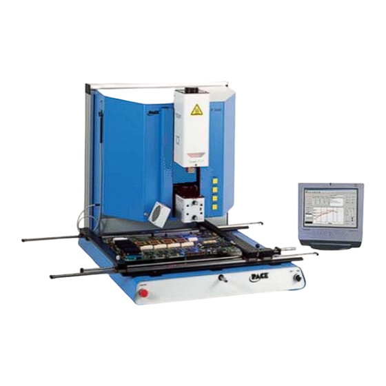
System Operations Manual TF 1700 BGA Rework Station Parts Identification Figure 1a A. Air Flow Meter This device is used to control and monitor the airflow through the reflow head. B. Sensor Inputs The sensor inputs are K-type thermo-couples. Measured temperatures are displayed through the PC software in real time for use in making profile graphs. - Page 5 System Operations Manual G. Optics Housing Contains the camera and beam splitter (prism). The housing extends and retracts automatically during operation and the lights for the optics will turn on/off automatically when the housing is extended/retracted. H. Bottom Side Heater Used to warm the PCB from the underside.
-
Page 6: Safety Information
Do not open rear panel without disconnecting the main power cable. 3. Features a. The TF 1700 and TF 2700 are ideal for post assembly rework, repair, and low volume/short run production operations. The TF 1700 and TF 2700 can remove and install PBGAs, CSPs, FCs, LGAs, LCC’s and other SMDs. - Page 7 System Operations Manual to use. The TF 1700 and TF2700 are a PC driven, semi-automated system that requires a Pentium ® 4 PC featuring Windows XP® Professional OS. The unique standard software package offers much more than just an operator interface.
-
Page 8: Set-Up
4. Set-Up a. Connect i. The TF 1700 and TF 2700 come configured to use the internal air pump. Both BGA Rework Stations may also be operated with an external N Supply. Select air or (nitrogen) source using the drop down box on the setup page. -
Page 9: Start Up
System Operations Manual Connection ii. Insert PC into brackets on back of BGA Rework Station. iii. Monitor 1. Connect power cord. 2. Connect video cable to the 9-pin connector of the PC. iv. Keyboard – connect cable to computer. v. Mouse – connect cable to computer. vi. - Page 10 System Operations Manual Figure 3a d. Inserting/changing nozzle. (Figure 3b) i. Insert proper size nozzle. The OD of the nozzle should be 3 mm larger than the outside of the component. If the proper nozzle size cannot fit onto the PCB due to adjacent components being to close, use a smaller nozzle or keep the nozzle approximately 1mm above the part.
- Page 11 System Operations Manual a. Software set up screen features. (Figure 4a) viii xvii xviii Figure 4a i. Set Password. Setup and profile settings can be password protected. ii. Set Language. Software text language can be changed. iii. Set temperature for Celsius or Fahrenheit. iv.
- Page 12 System Operations Manual xvi. Temperature sensors. Tests active thermocouple circuitry. xvii. Reset diagnostics. Must be clicked after any diagnostic test is performed to reset the tests to default settings. xviii. Run the activity log. Figure 4b shows the pre-heater indicator of the TF 2700.
-
Page 13: Alignment Screen Features
System Operations Manual b. Alignment Screen Features (Figure 5) viii Figure 5 i. Full Screen. Click on here to view image full screen. ii. Flip Image. Allows operator to flip the image horizontally or vertically. iii. Component/PCB alignment image. Proper alignment is viewed here showing the PCB pads directly under the component pads. -
Page 14: Production Screen Features
System Operations Manual c. Production Screen Features (Figure 6) viii Figure 6a i. Profile Name. Indicates currently selected profile. A new profile can be selected from a list of saved profiles by clicking on the arrow. ii. Record Manager. Profile information may be stored and exported in PDF file format. -
Page 15: Profile Development Screen Features
System Operations Manual Figure 6b shows the pre-heater indicator of the TF 2700. This feature indicates which pre- heater is on and the current temperature. To turn on or off individual secondary pre-heaters click on the graphic. While individual secondary pre-heaters can be turned on and off, they must all be set at the same temperature. - Page 16 System Operations Manual d. Profile Development Screen (Figure 7) viii Figure 7a i. Profile Name. Indicates currently selected profile. ii. Profile Manager. Temperature and time setting entered by the developer can be viewed managed here (Figure 7a). iii. Graph. A saved graph and, if thermocouples are used, an active trace graph are viewed here.
- Page 17 System Operations Manual Figure 7b xi. Heater. Click on Heater button during profile development to deactivate heater. xii. Cycle Start. Click on button to run profile during development. TF 2700 Pre-heater Indicator TF 2700 Pre-Heater Indicator. Indicates which pre- heater is on and the current temperature. To turn on or off individual secondary pre-heaters click on the graphic.
- Page 18 Liftoff. Select from Auto or Manual in removal mode by clicking. Flux Dip. Enable or disable flux dip operation by clicking. NOTE The TF 1700 airflow control is manual using the flow meter mounted on the front housing. The TF 2700 airflow control feature is operated using the PC software.
- Page 19 Flux Dip. Enable or disable flux dip operation by clicking. NOTE The TF 2700 airflow control feature is operated using the PC software. The TF 1700 airflow control is manual using the flow meter mounted on the front housing. www.paceworldwide.com...
-
Page 20: Inspection Screen Features
System Operations Manual Inspection Screen Features Inspection Screen (Figure 8a) i. Flip feature. Rotate or flip inspection image. ii. Inspection Image. The inspection image selected is viewed here. iii. (S) tab allows you to select video input source. (C) tab gives you access to TF1700 camera control when selected input source. - Page 21 System Operations Manual viii Capture Mode Figure 8b viii. Video Source. Select whether the image is from the BGA workstation (C) camera or (S) alternate source. ix. Mode. Allows operator to review library images (Fig 8a), capture images (Fig 8b), review saved images (Fig 8c), and create report (Fig 8d). x.
- Page 22 System Operations Manual xiii Review Saved Images Mode Figure 8c xii. Mode. Allows operator to review library images (Fig 8a), capture images (Fig 8b), review saved images (Fig 8c), and create report (Fig 8d). xiii. Select Image File. Opens folder containing image library. www.paceworldwide.com Page 22 of 50...
- Page 23 System Operations Manual Create Report Mode Figure 8d xiv. Mode Menu. Drop down menu revealing capture and image viewing options. Create Report. Captured images are imbedded in a five-page Adobe PDF document. Page 1 shows four captured images. Remaining pages show individual images indicated by the red box on the right-hand side of the page.
- Page 24 System Operations Manual g. Prism Calibration – This step is required to ensure the prism is properly aligned so when the software shows the PCB and component visually aligned, they are actually physically aligned. i. Select setup screen. (Figure 9) Prism Calibration Figure 9 ii.
- Page 25 System Operations Manual v. Align PCB so red laser sighting light is roughly centered on BGA. (Figure 10) Figure 11 vi. Mouse click on green button, “Pickup.” vii. Mouse click “OK” when message prompt (Please load PCB into board holder) appears. Camera Housing Figure 11 viii.
- Page 26 System Operations Manual Figure 12 xii. If solder ball on part do not line up with holes on test PCB, adjust prism until it is. 1. Loosen the setscrews from the light adjustment knobs (Figure 14) 2. Remove the knobs 3.
-
Page 27: Operation
6. Operation Note: It is recommended that the TF 1700 and TF 2700 be turned on for at least 10 minutes before use to ensure the bottom side heater has reached its set temperature and stabilized. Once the bottom side heater is at operating temperature it will deliver consistent heating, ensuring highly repeatable heating from operation to operation. - Page 28 Mouse click on the green button again to switch to the alignment screen and lower component to focus point. (Figure 5) WARNING: TF 1700 USERS ONLY When using the optional 65mm x 65mm component nest, (P/N 6000-0285) Nest must be removed from camera housing before camera is allowed to retract.
- Page 29 System Operations Manual Flux Tray Figure 19 Zoom in and align using the X, Y, and theta axis adjustments until the component is aligned. (Figures 5 & 20) Theta Left and Right Forward and Back Figure 20 xvi. Mouse click on the green button, “Place” to lower the component. (Figure 21) Nozzle on board ready to start...
-
Page 30: Component Removal
System Operations Manual xviii. Allow the PCB to cool and remove. b. Component removal – Note: If at any time you need to abort the process mouse click on the Red Home button. i. Mouse click on Production to switch to the production screen. (Figure 6) ii. - Page 31 A good reference is to use the same cool down rate as for ramp up. The cooling fan on the TF 1700 and TF 2700 will remain on for a minimum of 50 seconds from the start of the cool down cycle. Some types of components (like CBGAs) should be allowed to cool without external assistance from the cooling fan.
-
Page 32: Profile Development
Cleaning the Blower Filter. Clean the filter every three months. i. Open the cover on the back of the TF 1700 or TF 2700. (Figure 21) ii. Identify the blower pump, mounted on the base of the machine. - Page 33 The camera glass window should be cleaned periodically with glass cleaner and a soft cloth. Pump filter housing Screw Figure 23b shows the TF 2700 blower pump. Maintenance instructions are the same for both the TF 1700 and the TF 2700. TF2700 shown Figure 23b www.paceworldwide.com Page 33 of 50...
-
Page 34: Heater Replacement
Maintenance beyond this should only be completed by a qualified PACE service technician. Heater Replacement It is recommended you return the machine to PACE, Inc. or call a PACE representative to replace the heater element. CAUTION: REMOVE POWER CORD FROM MACHINE. - Page 35 System Operations Manual 4. Slide the metal retainers up the lower rail assemblies after the removal of the rail covers on the reflow head assembly. Be sure that the metal retainers are installed on the rails. Important Note: Failure to perform this operation may result in loss of the ball bearings that are contained within the rails.
- Page 36 System Operations Manual 7. Now you can disconnect the cooling fan cables, 1 on each side. Once these two Figure 26 cables have been disconnected you can remove the cover. Figure 27 8. Disconnect the main heater wiring on the left side of the heater assembly.
- Page 37 System Operations Manual 10. Remove the four pick solenoid sensor cover screws. Requires 3/32” hex wrench 11. Remove the pick solenoid sensor. Requires 3/32” hex wrench Figure 30 12. Remove the ground wire that is located on the left side of the heater assembly. Requires 3/32”...
- Page 38 System Operations Manual 13. Disconnect the hose on the top of the heater assembly. Figure 33 14. Disconnect the hose on the right of the heater assembly. Figure 34 15. Open the rear door (requires 4mm hex wrench) and disconnect the sensor flag as shown.
- Page 39 System Operations Manual Figure 36 17. From the back, pull the remaining disconnected wires through the heater mounting plate. Figure 37 18. Remove the 16 hex socket head screws holding the heater assembly to the rails. Be sure to hold the assembly or it will fall when the last screw is removed.
- Page 40 System Operations Manual Installation Carefully install the new heater assembly on the rails. Guide the vacuum line and tubing through the mounting plate. Make sure that the hoses are not pinched. Refer to figure Make sure that the belt bracket rests on the lift bracket before installing the mounting screws.
- Page 41 System Operations Manual 4. Pull the disconnected wires back through the heater mounting plate. Figure 42 5. Run the sensor wires through front panel the way they came out, reconnect and tie. Make sure they are connected to the appropriate one. Rewind the protective wire spiral covering over the wires.
- Page 42 System Operations Manual 6. Reconnect the vacuum line support bracket. Install a new ty-wrap. Figure 44 7. Reconnect the hose on the right of the heater assembly. Figure 45 8. Reconnect the hose on the top of the heater assembly. Figure 46 9.
- Page 43 System Operations Manual 10. Reinstall the pick solenoid sensor. Figure 48 11. Install the solenoid pick sensor cover and four screws. 12. Reconnect the pick solenoid wiring on the left side of the heater assembly. Figure 49 13. Reconnect the main heater wiring on the left side of the heater assembly.
- Page 44 System Operations Manual Figure 51 15. Put the heater cover back on making sure not to pinch hoses or wires. Reinstall the four screws. Figure 52 17. Remove the metal retainers from the lower rail assemblies. Figure 53 18. Remove the installed hex head screw in the rails to avoid the accidental removal of the reflow head assembly.
-
Page 45: Adjustments And Alignments
System Operations Manual 20. Reinstall the nozzle and vacuum pick. 21. Test the heater. Adjustments and Alignments 1. Platform planarity. This procedure is only necessary if the vacuum pick does not pick up the component. a. Insert the large vacuum pick. b. - Page 46 System Operations Manual Adjust the smaller four screws to bring the platform and PCB level with the vacuum pick. Loosening a screw will raise that portion of the platform. Tightening a screw will lower that portion of the platform. To keep the screws tight for every bit you loosen a screw, tighten the opposite screw equally as much.
- Page 47 System Operations Manual iii. In the back, loosen the screw in the center on the back of the camera housing. iv. Rotate the camera until the left and right sides of the nozzle are centered between the sides of the viewing area. Tighten the screws.
-
Page 48: Regulation
Adjust the laser to a spot roughly in the center of the component and tighten screws. Laser adjustment block Regulation a. This product is CE approved. b. PACE products meet or exceed all applicable military and civilian EOS/ESD, temperature stability and other specifications, including ANSI-J-STD-001, IPC- 7711, IPC-7721 and IPC-A-610. www.paceworldwide.com Page 48 of 50... -
Page 49: Service And Warranty
Warranty service may be obtained by contacting the appropriate PACE Company or local Authorized PACE distributor as set forth below to determine if return any item is required or, if repairs can be made, by the user in the field. - Page 50 (888)-535-PACE Fax: (301) 498-3252 (44) 1908-277777 PACE Incorporated retains the right to make changes to specifications contained herein at any time, without notice. Contact your local authorized PACE Distributor or PACE Incorporated to obtain the latest specifications. The following are trademarks and/or service marks of PACE, Incorporated, MD, USA.
Need help?
Do you have a question about the TF 1700 and is the answer not in the manual?
Questions and answers