
Related Manuals for MKS MODUCELL 325 Series


Summary of Contents for MKS MODUCELL 325 Series
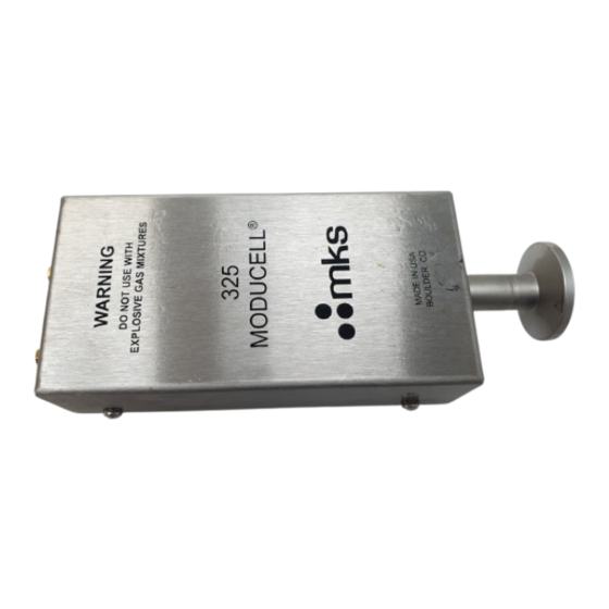
- Page 1 Series 325 MODUCELL Pirani Vacuum ® Sensor/Transducer Instruction Manual Instruction manual part number 103250029 Revision B - May 2020...
- Page 2 Andover MA, 01810 USA Phone: +1-833-986-1686 Email: insidesales@mksinst.com Visit our website at www.mksinst.com Instruction Manual © 2020 MKS Instruments, Inc. All rights reserved. ® MODUCELL is a registered trademark and mksinst is a trademark of MKS Instruments, Inc. All other trademarks and registered trademarks are the properties of their respective...
-
Page 3: Table Of Contents
Table of Contents Chapter 1 General Information ............. . . 5 Receiving Inspection . - Page 4 Replacing the Sensor Tube ............31 6.7.1 Disassemble the MODUCELL .
-
Page 5: Chapter 1 General Information
Any damaged material including all containers and packaging should be held for carrier inspection. Contact MKS Customer Support for assistance if your shipment is not correct for reasons other than shipping damage. -
Page 6: Customer Service / Technical Support
1 General Information 1.5 Customer Service / Technical Support Some minor problems are readily corrected on site. If the product requires service, contact the MKS Technical Support Department at +1-833-986-1686. If the product must be returned to the factory for service, request a Return Material Authorization (RMA) from MKS. Do not return products without first obtaining an RMA. -
Page 7: Safety
These instructions do not and cannot provide for every contingency that may arise in connection with the installation, operation, or maintenance of this product. If you require further assistance, contact MKS. This product was designed and tested to offer reasonably safe service provided it is installed, operated, and serviced in strict accordance with these safety instructions. -
Page 8: Responsibility
MKS literature including, but not limited to, manuals, instructions, bulletins, communications, and recommendations. For emergencies and for product safety related matters, contact the MKS Customer Service Department. See Section 1.5 or Section 6.1 for detailed information regarding how to contact MKS Customer Service Representatives. Series 325 Moducell Vacuum Sensor... -
Page 9: Grounding Requirements
2 Safety 2.3 Grounding Requirements See Grounding, Section 4.1 in the Installation chapter for more detailed requirements regarding gauge and system grounding. Proper Grounding All components of a vacuum system used with this or any similar high voltage product must be maintained at Earth ground for safe operation. -
Page 10: High Voltage
2 Safety 2.4 High Voltage High Voltage is present in the unit when electrical power is applied to the electronics enclosure. Hazardous voltages may still be present for some time after disconnecting power to the electronics enclosure. Refer to the Installation and Service chapters for more information. High Voltage Be aware that when high voltage is present in any vacuum system, a life threatening electrical shock hazard may exist... -
Page 11: Over Pressure Conditions
2 Safety 2.5 Over Pressure Conditions Explosive Environment Do not use the Series 325 Sensor in an environment of explosive or combustible gases or gas mixtures. Operation of any electrical instrument in such an environment constitutes a definite safety hazard. Do not use the product to measure the pressure of explosive gases or gas mixtures. -
Page 12: Damage Requiring Service
Because of the danger of introducing additional hazards, do not install substitute parts or perform any unauthorized modification to the product. Return the product to a service facility designated by MKS for service and repair to ensure that safety features are maintained. Do not use this product if it has unauthorized modifications. -
Page 13: Chapter 3 Specifications
3 Specifications Chapter 3 3Specifications 3.1 General Description ® The Series 325 MODUCELL Pirani Vacuum Sensors are a heat-loss manometer which infers the pressure of a gas by measuring thermal loss from a heated wire. Pirani sensors use the pressure- dependent thermal energy transport from a hot wire to measure pressure. -
Page 14: Specifications
3 Specifications 3.5 Specifications Table 3-1 Specifications for the Series 423 I-Mag Sensor Parameter Specification Performance Torr: 1.0 x 10 to 100 Measurement Range for N / Air mbar: 1.3 x 10 to 1.3 x 10 Pascal:1.3 x 10- to 1.3 x 10 Useful Setpoint Range Torr: 5.0 x 10 to 30... -
Page 15: Chapter 4 Installation
If particulates in the system are common, it is necessary to keep them from entering the Sensor using a screen or porous filter at the port. A centering ring with a screen, MKS p/n 100318601 is useful. Connect the Sensor to the Vacuum System Mount the Sensor to a grounded vacuum system. - Page 16 4 Installation Notice A solid electrical connection between the sensor tube and the grounded vacuum system must be used to shield the tube element from external power sources. In applications where the system may be exposed to large voltage fluctuations, a centering ring (HPSTM part # 100318601) with a screen should be installed, and the screen and tube then grounded.
-
Page 17: Electrical Connections
4 Installation For an O-ring Compression Seal fitting: The MODUCELL can also use a ½" O-ring compression seal acting on the tubing above the thread, but the O-ring seal cannot be used for positive pressure applications. 4.3 Electrical Connections Do not connect or disconnect any electrical connectors while power is applied to the equipment (hot swapping). -
Page 18: Inductive Loads And Arc Suppression
4 Installation Do not ground pin 7 to pin 4. Doing this will cause a sudden voltage drop on the ground wire, resulting in a large transient in the analog output voltage. Pin 7 must be grounded at the power supply. -
Page 19: Adjust The Set Point
4 Installation 4.3.3 Adjust the Set Point The set point relay can be adjusted to actuate at a particular pressure, using the MODUCELL's built- in potentiometer. To adjust the set point relay to a particular pressure, use the data in Figure 5-1 and Figure 5-2 to find the corresponding voltage. - Page 20 4 Installation Notes: Series 325 Moducell Vacuum Sensor Instruction Manual - 103250029...
-
Page 21: Chapter 5 Operation
5 Operation Chapter 5 1Operation 5.1 Theory of Operation The MODUCELL is a heat-loss manometer which infers the pressure of a gas by measuring thermal loss from a heated wire. 5.1.1 Theory of the Thermal Conductivity Gauge The MODUCELL uses a wire as one arm of a balanced Wheatstone bridge. The bridge amplifier maintains the sensor wire at a constant temperature, and the amplifier output varies with the energy loss. -
Page 22: Open Filament Detector
5 Operation 5.1.5 Open Filament Detector Op amp U2a acts as a comparator that monitors the filament side of the bridge. If the sensor filament breaks, the inverting input of the op amp falls below the 80 mV reference voltage from R29, turning on transistor Q1 which prevents transistor Q2 from turning on. -
Page 23: Gas Other Than Air Or Nitrogen
5.3 Gas Other than Air or Nitrogen Before using the MODUCELL to measure pressure of gases other than air or nitrogen, read and understand this section. Contact the MKS Customer Service Department if additional information is needed. The MODUCELL is designed to give voltage output according to the graph in Figure 5-1 or the table in Figure 5-2 for air or nitrogen. -
Page 24: Nitrogen Equivalent Pressure And Voltage
5 Operation 5.3.1 Nitrogen Equivalent Pressure and Voltage The thermal loss from a heated sensor element is a function of the transporting gas (see page A.1, Theory of the Thermal Conductivity Gauge.) Since the MODUCELL is such a sensor, the voltage output depends upon the gas being measured. -
Page 25: Energy Transfer And Measurement Limits
5 Operation Figure 5-3: Equations to Convert Voltage to Pressure 5.5 Energy Transfer and Measurement Limits 5.5.1 The Energy Transfer Equation The mechanism of energy transfer between the wire and the gas in a heat- loss manometer like the MODUCELL depends upon the pressure range. For pressures below 10-1 Torr, it is possible to derive an equation showing a linear relationship between the thermal energy loss to the gas E and the pressure P, where: Figure 5-4: Energy Transfer Equation... -
Page 26: Measurement Limits
5 Operation and for the particular gas, a is the accommodation coefficient g is the ratio of the specific heat at constant pressure to that at constant volume M is the molecular weight of the gas is the temperature of the wire is the temperature of the gas 5.5.2 Measurement Limits At pressures above 100 Torr for nitrogen, and widely differing values for other gases, the gas acts... -
Page 27: Chapter 6 Service & Maintenance
2Service & Maintenance 6.1 Customer Service / Technical Support Some minor problems are readily corrected on site. If the product requires service, contact the MKS Technical Support Department at +1-833-986-1686. If the product must be returned to the factory for service, request a Return Material Authorization (RMA) from MKS. Do not return products without first obtaining an RMA. -
Page 28: Damage Requiring Service
Return the product to a service facility designated by MKS for service and repair to ensure that safety features are maintained. Do not use this product if it has unauthorized modifications. -
Page 29: Troubleshooting
A troubleshooting chart for the MODUCELL follows. With this guide, you should be able to locate and remedy the cause of a fault. The problems listed here might occur on the system assembly level. Other faults are usually not serviceable by the user, and the faulty unit should be returned to MKS to be repaired. -
Page 30: Cleaning The Moducell Case And Sensor Tube
6 Service & Maintenance Electrostatic Discharge Use a grounded, conductive work surface. Wear a high impedance ground strap for personnel protection. Circuit boards and electronic components could be damaged by electrostatic discharge. Use conductive or static dissipative envelopes to store or ship static sensitive devices or printed circuit boards. -
Page 31: Replacing The Sensor Tube
6 Service & Maintenance Figure 6-2: Checking Resistance 6.7 Replacing the Sensor Tube 6.7.1 Disassemble the MODUCELL Remove the four Phillips head screws that secure the cover on the sides. With a low wattage soldering iron, de-solder the two wires that connect the tube to terminals F1 and F2 (Figure 6-2). - Page 32 6 Service & Maintenance Figure 6-3: End of Tube View Install the two 6-32 Phillips head screws to secure the tube in place. Solder the two wires from the tube to F1 and F2. Clip off any excess wire. Be sure the clippings do not fall into the enclosure.
- Page 33 6 Service & Maintenance Figure 6-5: PC Board Thermistor and Potentiometer Series 325 Moducell Vacuum Sensor Instruction Manual - #103250029...
- Page 34 6 Service & Maintenance Series 325 Moducell Vacuum Sensor Instruction Manual - 103250029...
-
Page 35: Index
Index 7, 8 Caution Notices & Symbols Receiving Inspection Damage requiring service Safety 7, 8 Cautions & Warnings Service Grounding Contact Information Gauge to Vacuum Chamber 6, 27 Guidelines Requirements Service guidelines Specifications High Voltage Storage Introduction Terms General Description used in this chapter Improper Use Intended Use... - Page 36 Series 325 Moducell Vacuum Sensor Instruction Manual - 103250029...
- Page 38 Series 325 ® MODUCELL Pirani Vacuum Sensor/Transducer Customer Service / Technical Support: MKS Global Headquarters 2 Tech Drive, Suite 201 Andover MA, 01810 USA Phone: +1-833-986-1686 Email: insidesales@mksinst.com Visit our website at www.mksinst.com Instruction Manual Instruction manual part number 103250029...
Need help?
Do you have a question about the MODUCELL 325 Series and is the answer not in the manual?
Questions and answers