
Related Manuals for MKS 943 Series


Summary of Contents for MKS 943 Series
- Page 1 Series 943 Cold Cathode Vacuum Sensor System Instruction Manual Instruction manual part number 100009887 Revision D - May 2020...
- Page 3 Visit our website at www.mksinst.com Instruction Manual © 2020 MKS Instruments, Inc. All rights reserved. ® I-Mag is a registered trademark, and IgniTorr and mksinst are trademarks of MKS Instruments, Inc. All other trademarks and registered trademarks are the properties of their respective owners.
- Page 4 Series 943 Cold Cathode Vacuum Sensor System Catalog numbers for Series 943 Cold Cathode Vacuum Sensor System 943-A-120V50-PA-PC 943-A-120V50-TR-NA 943-A-120V50-TR-PC 943-A-120V60-PA-PC 943-A-120V60-TR-PC 943-A-120V60-TR-PC-01 943-A-120V60-TR-PC-02 943-A-120V60-TR-NA 943-A-220V50-PA-PC 943-A-220V50-TR-NA 943-A-220V50-TR-PC 943-A-220V60-PA-PC 943-A-220V60-TR-NA 943-A-220V60-TR-PC 943-A-220V60-PA-PC-02...
-
Page 5: Table Of Contents
Table of Contents Chapter 1 General Information ............. . . 7 Receiving Inspection . - Page 6 Troubleshooting ..............37 Contaminated 943 Sensor .
-
Page 7: Chapter 1 General Information
Any damaged material including all containers and packaging should be held for carrier inspection. Contact MKS Customer Support for assistance if your shipment is not correct for reasons other than shipping damage. -
Page 8: Customer Service / Technical Support
1 General Information 1.5 Customer Service / Technical Support Some minor problems are readily corrected on site. If the product requires service, contact the MKS Technical Support Department at +1-833-986-1686. If the product must be returned to the factory for service, request a Return Material Authorization (RMA) from MKS. Do not return products without first obtaining an RMA. -
Page 9: Safety
These instructions do not and cannot provide for every contingency that may arise in connection with the installation, operation, or maintenance of this product. If you require further assistance, contact MKS. This product was designed and tested to offer reasonably safe service provided it is installed, operated, and serviced in strict accordance with these safety instructions. -
Page 10: Responsibility
For emergencies and for product safety related matters, contact the MKS Customer Service Department. See Section 1.5 or Section 6.6 for detailed information regarding how to contact MKS Customer Service Representatives. Series 943 Cold Cathode Vacuum Sensor... -
Page 11: Grounding Requirements
2 Safety 2.3 Grounding Requirements See Grounding, Section 4.1.2 in the Installation chapter for more detailed requirements regarding gauge and system grounding. Proper Grounding All components of a vacuum system used with this or any similar high voltage product must be maintained at Earth ground for safe operation. -
Page 12: High Voltage
2 Safety 2.4 High Voltage High Voltage is present in the unit when electrical power is applied to the electronics enclosure. Hazardous voltages may still be present for some time after disconnecting power to the electronics enclosure. Refer to the Installation and Service chapters for more information. High Voltage Be aware that when high voltage is present in any vacuum system, a life threatening electrical shock hazard may exist... -
Page 13: Over Pressure Conditions
2 Safety 2.5 Over Pressure Conditions Explosive Environment Do not use the Series 943 Vacuum Sensor System in an environment of explosive or combustible gases or gas mixtures. Operation of any electrical instrument in such an environment constitutes a definite safety hazard. Do not use the product to measure the pressure of explosive gases or gas mixtures. -
Page 14: Damage Requiring Service
Because of the danger of introducing additional hazards, do not install substitute parts or perform any unauthorized modification to the product. Return the product to a service facility designated by MKS for service and repair to ensure that safety features are maintained. Do not use this product if it has unauthorized modifications. -
Page 15: Chapter 3 Specifications
3 Specifications Chapter 3 3Specifications 3.1 General Description The Series 943 Digital, Cold Cathode Vacuum Sensor System provides accurate and reliable data for processes which need pressure measurement from 10 Torr up to 10 Torr. The System is easy to use and is designed for versatility, reliability, and economy. 3.2 Intended Use / Applications The Series 943 Controller is useful either as a small system controller or as a module in more sophisticated pressure control environments. -
Page 16: Specifications
3 Specifications 3.4 Specifications Table 3-1 Specifications for the Series 943 Digital, Cold Cathode Vacuum Sensor Parameter Specification Performance Torr: 1.0 x 10 to 1.0 x 10 Measurement Range for N / Air mbar: 1.3 x 10 to 1.3 x 10 Do NOT use this product with flammable or explosive gases. - Page 17 3 Specifications Table 3-1 Specifications for the Series 943 Digital, Cold Cathode Vacuum Sensor Parameter Specification Operating Temperature Range 0° to 70°C (32° to 158°F) Maximum Bakeout Temperature Series 421 - 250°C (482°F) when backshell subassembly Without Controller or Cables removed, 125°C (257°F) Series 423 - 500°C (932°F) for CF flange model, magnet removed Diameter...
- Page 18 3 Specifications Notes: Series 943 Cold Cathode Vacuum Sensor Instruction Manual - #100009887...
-
Page 19: Chapter 4 Installation
4 Installation Chapter 4 4Installation 4.1 Mounting the Controller The Series 943 Controller is designed for either panel mounting or stand-alone use. An optional hardware kit is available for mounting the Controller into a standard ¼ DIN cutout in a panel up to 3/16-inch thick (see Section 6.7, Accessories). -
Page 20: Fuse Replacement
4 Installation Do not exceed the rated line voltage of your unit. Electrical shock may result. 4.1.3 Fuse Replacement The Series 943 Controller has a combined fuse holder and power inlet on the rear panel. Replace the fuse following the steps below. Unplug the power cord from the power source and the Controller. -
Page 21: Logarithmic Analog Output
4 Installation Notice Do not inadvertently short circuit the set point relay terminals to the analog output voltage If both the analog output and the high voltage enable are being used, use separate ground wires for each and connect them only at the Accessory port. Otherwise, the analog voltage may be incorrect. 4.1.5 Logarithmic Analog Output Connecting to pins 11 and 12 provides a logarithmically-scaled, pressure dependent voltage V from 1 to 9 V. - Page 22 4 Installation Figure 4-2 Cold Cathode Analog Output Voltage vs. Pressure Series 943 Cold Cathode Vacuum Sensor Instruction Manual - #100009887...
-
Page 23: Remote High Voltage Enable/Disable
4 Installation Figure 4-3 Cold Cathode Analog Output Voltage vs. Pressure 4.1.7 Remote High Voltage Enable/Disable The cold cathode sensor's high voltage may be turned OFF or ON using a set point from a low vacuum sensor, such as a Pirani or convection Pirani. Use pins 9 and 10 to connect the Controller to the sensor for this external control. -
Page 24: Relay Inductive Loads And Arc Suppression
4 Installation Table 4-3: Remote High Voltage Enable/Disable High voltage is: Pin 9 is: Disconnected ON (sensor enabled) Connected to a “logic Hi” of +5V Connected to pin 10 through a switch or relay contact OFF (sensor disabled) connected to a “logic Low” of 0V 4.1.8 Relay Inductive Loads and Arc Suppression If the set point relays are used to switch inductive loads, e.g., solenoids, relays, transformers, etc., the arcing of the relay contacts may interfere with Controller operation or reduce relay contact life. -
Page 25: Installing A Series 943 System Sensor
4 Installation 4.2 Installing a Series 943 System Sensor The Series 943 Controller must be turned OFF before connecting or disconnecting a sensor cable from the sensor or Controller. 4.2.1 Locating a Cold Cathode Sensor Locate a cold cathode sensor where it can measure process chamber or manifold pressure. Install it away from pumps, vibration sources, and gas sources to give the most representative values. - Page 26 4 Installation Notice The Series 423 Sensor has a strong magnetic field. Be careful when using it around tools and other equipment. When replacing the magnet, note that it is keyed to the sensor body to protect the feedthrough pins from damage.
-
Page 27: Chapter 5 Operation
The MKS IgniTorr™, an optional cold cathode starting device initiates the ionization process in cold cathode sensors, starting UHV pressure readings in seconds. - Page 28 Torr. This extends the measuring range of the cold cathode to 10 Torr. MKS cold cathode sensors use an inverted magnetron with separate feedthroughs for the anode high voltage and the cathode current. This geometry uses a cylindrical cathode, a central wire anode, and external cylindrical magnet which provides an axial field.
-
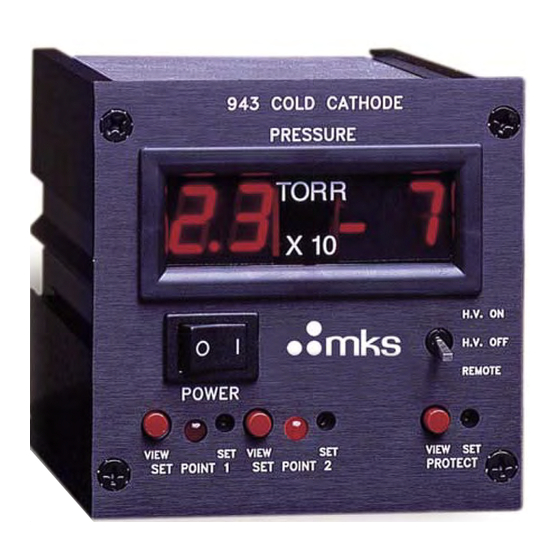
Page 29: 943 Controller Front / Rear Panels
5 Operation 5.2 943 Controller Front / Rear Panels Figure 5-2: 943 Controller Front and Rear Panels 5.3 Series 943 Circuit Description The Series 943 Controller is an analog instrument which has four basic circuits to control the cold cathode sensor and uses signals from the sensor to display pressure, operate the set point relays, and supply analog voltage-vs.-pressure outputs. -
Page 30: Electrometer
5 Operation 5.3.2 Electrometer The electrometer performs a logarithmic conversion to measure the sensor tube's current and high voltage. This electrometer has a dynamic range wide enough to cover the entire pressure range with no electronic range changing. 5.3.3 Analog Processing The processing circuitry combines the electrometer signals and scales the result to produce a pressure dependent voltage signal. -
Page 31: Using The Series 943 System With Gases Other Than Air Or N2
5.4 Using the Series 943 System with Gases other than Air or N Before using the Series 943 Controller to measure pressure of gases other than air or nitrogen, read and understand this section. If additional information is needed, contact MKS Customer Support at: phone +1-833-986-1686 or email insidesales@mksinst.com. -
Page 32: Calibrating For Other Gases
5 Operation Figure 5-5 shows the correction factors needed to obtain curves for selected gases other than air/ nitrogen. You can make your own graph from this information. Figure 5-5: True Pressure vs. Indicated Pressure Correction Factors 5.4.1 Calibrating for Other Gases Air calibration is indistinguishable from nitrogen. -
Page 33: Reading Pressure
5 Operation 5.5 Reading Pressure Notice A sensor must be connected to the Controller before turning it ON. Set the Controller's high voltage switch to H.V. OFF. Turn ON the power switch. OFF will appear on the display. If the high voltage switch was left in the H.V. ON or H.V. Remote position before power ON, PRO (Protect) will appear. - Page 34 5 Operation Use a small screwdriver to adjust its potentiometer until the reading coincides with the desired set point pressure. If the protect set point turns the high voltage OFF, PRO will appear on the display. Turn OFF the high voltage switch and then back ON again to enable the high voltage. The protect set point cannot work if the system's pressure is in the sensor's "roll-back"...
-
Page 35: Chapter 6 Service & Maintenance
6 Service & Maintenance Chapter 6 2Service & Maintenance 6.1 Introduction The procedures in this section provide instructions for normal service issues that may be required during use of the Series 943 Cold Cathode Vacuum Sensor System. 6.2 Service Guidelines Some minor difficulties are readily corrected in the field. -
Page 36: Damage Requiring Service
Return the product to a service facility designated by MKS for service and repair to ensure that safety features are maintained. Do not use this product if it has unauthorized modifications. -
Page 37: Troubleshooting
(see Section 5. Controller may be out of calibration. 6.7, Accessories). 6. Gas in system may not be air or Return to MKS for repair. nitrogen Use a correct conversion factor. No pressure reading on Controller might not be plugged into... -
Page 38: Contaminated 943 Sensor
6 Service & Maintenance 6.5 Contaminated 943 Sensor If pressure readings appear to be erratic, the Sensor tube may be contaminated. Inspect it visually. If contamination is visible, you should replace the internal components with an Internal Rebuild Kit (see Section 6.7, Accessories). Depending on the degree of contamination and application of the sensor, the internal parts may be cleaned - either ultrasonically, with mild abrasives, or chemically. -
Page 39: Disassembly
6 Service & Maintenance 6.5.1 Disassembly Tools required: clean tweezers and smooth-jaw, needle-nose pliers. Wear cleanroom gloves during all handling and cleaning procedure. See Section 6-1 for disassembly and cleaning, and Section 6-2 for final reassembly. Delicate Internal Components Do not bend the anode (8) or the leaf spring (9) on the ion current feed through pin (13) when disassembling or assembling the Sensor;... -
Page 40: Reassemble The Sensor
6 Service & Maintenance 6.5.3 Reassemble the Sensor Check the anode (8). It should be straight and centered with the sensor body (7) for proper operation. Roll the sensor body on a flat surface and look for any radial run out motion. Install the ground shield 6 using tweezers. -
Page 41: Customer Service / Technical Support
6 Service & Maintenance 6.6 Customer Service / Technical Support Some minor problems are readily corrected on site. If the product requires service, contact the MKS Technical Support Department at +1-833-986-1686. If the product must be returned to the factory for service, request a Return Material Authorization (RMA) from MKS. -
Page 42: Accessories/ Spare Parts
6 Service & Maintenance 6.7 Accessories/ Spare Parts Table 6-2 Series 943 Spare Parts List Item Part # Item Part # Cable for Series 421 Cold Cathode Sensor Series 421 Cold Cathode Sensor 10 ft (3.0 m) 100006171 KF 25 104210004 25 ft (7.6 m) 100006172... -
Page 43: Index
Index 9, 10 Caution Notices & Symbols Over Pressure Conditions Damage requiring service Receiving Inspection Grounding Safety 9, 10 Gauge to Vacuum Chamber Cautions & Warnings Requirements Service Contact Information 8, 41 Guidelines High Voltage Service guidelines Specifications Introduction Storage General Description Improper Use 9, 10... - Page 44 Series 943 Cold Cathode Vacuum Sensor Instruction Manual - #100009887...
- Page 46 Series 943 Cold Cathode Vacuum Sensor System Customer Service / Technical Support: MKS Global Headquarters 2 Tech Drive, Suite 201 Andover MA, 01810 USA Phone: +1-833-986-1686 Email: insidesales@mksinst.com Visit our website at www.mksinst.com Instruction Manual Instruction manual part number 100009887...
Need help?
Do you have a question about the 943 Series and is the answer not in the manual?
Questions and answers