Table of Contents
Advertisement
Quick Links
Installation Instructions
Thank you for choosing our product! We strive to provide the best
quality and services for our customers. Would you kindly share your
experience on Amazon if you are satisfied? Should you have any
issues, please don't hesitate to contact us.
Telephone:
1-800-556-6806 Mon-Fri 10am - 6pm (PST) (USA) (CAN)
Email:
supportus@perlesmith.com (US/CA/DE/UK/FR/IT/ES/JP/AU)
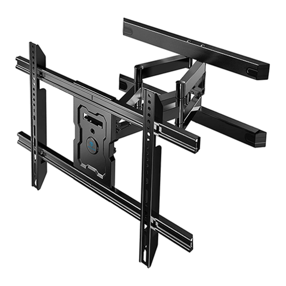
Max VESA:
600X400 mm/24X16 in.
PSLFK5
V1.0
Advertisement
Table of Contents

Related Manuals for Perlesmith PSLFK5


Summary of Contents for Perlesmith PSLFK5
- Page 1 V1.0 Max VESA: 600X400 mm/24X16 in. PSLFK5 Thank you for choosing our product! We strive to provide the best quality and services for our customers. Would you kindly share your experience on Amazon if you are satisfied? Should you have any issues, please don't hesitate to contact us.
-
Page 2: Important Safety Information
We hereby disclaim any liability for injury or damage arising from incorrect assembly, incorrect mounting, or incorrect use of this product. •DO NOT INSTALL INTO DRYWALL ALONE. •Please check www.perlesmith.com for more products and company information. Tools Needed (Not lncluded) Stud Finder... -
Page 3: Supplied Hardware
Supplied Hardware Hardware for Attaching TV Bracket to TV Spacers Washers [If necessary] M6/M8 2.5mm 10mm 22mm TV Screws [Only one size fits your TV] M6 x 14mm M6 x 20mm M6 x 35mm M8 x 50mm M8 x 16mm M8 x 25mm M8 x 35mm Arm Assembly/Wall Plate... - Page 4 Step 1 Install the Extensions [03] to Arm Assembly/Wall Plate[01] Step 2 Attach the Arm Assembly/Wall Plate [01] to Wall For wood stud installation, follow STEP 2A For concrete installation, follow STEP 2B Step 2A Wood Stud Option WARNING: ●Avoid potential personal injury or property damage! DO NOT over-tighten the lag bolts [A1].
- Page 5 2A-1 Use a stud finder(not included) to locate wood studs. Mark the edge and center locations. 2A-2 Ensure alignment using the bubble level. Position the wall plate template[08] at your desired height and line up the holes with your stud center line. Level the template and mark the holes.
- Page 6 Step 2B Solid Concrete or Concrete Block Option WARNING: ●Avoid potential personal injury or property damage! DO NOT over-tighten the lag bolts [A1]. Tighten the lag bolts [A1] only until the washers [A2] are pulled firmly against the wall plate. Wall ●Ensure the arm assembly/wall plate[01] is securely fastened to the Anchor...
- Page 7 2B-3 Use the hammer to knock A1 A2 anchors [A3] into the wall. Install the arm assembly/wall plate [01] using lag bolts [A1], washers [A2] and anchors [A3]. Be sure the anchors [A3] are seated flush with the concrete surface. Tighten the lag bolts [A1] only until the washers [A2] are pulled firmly against the 13mm wall plate.
- Page 8 Step 4 Check TV Hole Pattern and Select TV Screws 100 mm ≈ 4 in. 200 mm ≈ 7 7/8 in. 300 mm ≈ 11 3/4 in. 400 mm ≈ 15 3/4 in. 600 mm ≈ 23 6/10 in. Only one screw size fits your TV. Step 5 Select Spacers (if needed) NO SPACER...
- Page 9 Too Short Too Long Step 6 Secure the TV Brackets [02] to Your TV No Spacer With Spacer Alternate Spacer Setups Hang the TV onto the Arm Assembly/Wall Plate [01] Step 7 HEAVY! You may need assistance with this step.
-
Page 10: Level Adjustment
Step 8 Level Adjustment Loosen Tighten 1. Loosen the two screws [S] on the rear of arm plate [01] , using the hex key. 2. Level your TV. 3. Retighten screws [S] to secure in place. Step 9 Tilt Adjustment Tighten Loosen 1. - Page 11 Step 10 Manage Cables...
- Page 12 Would you kindly share your experience on Amazon if you are satisfied? Should you have any issues, please don't hesitate to contact us. Telephone: 1-800-556-6806 Mon-Fri 10am - 6pm (PST) (USA) (CAN) Email: supportus@perlesmith.com (US/CA/DE/UK/FR/IT/ES/JP/AU)
Need help?
Do you have a question about the PSLFK5 and is the answer not in the manual?
Questions and answers