Table of Contents
Advertisement
Quick Links
Carefully read and understand this instruction manual before using the lift truck.
It contains all information relating to operation, handling and lift truck equipment,
This document also contains precautions for use, as well as information on the servicing and routine maintenance required
WARNING ! BE CAREFUL ! YOUR SAFETY OR THE SAFETY OF THE LIFT TRUCK IS AT RISK.
- This manual has been produced on the basis of the equipment list and the technical characteristics
given at the time of its design.
- The level of equipment of the lift truck depends on the options chosen and the country of sale.
- According to the lift truck options and the date of sale, certain items of equipment/functions described
herein may not be available.
- Descriptions and figures are non binding.
- MANITOU reserves the right to change its models and their equipment without being required to
update this manual.
- The MANITOU network, consisting exclusively of qualified professionals, is at your disposal to answer
all your questions.
- This manual is an integral part of the lift truck.
- It is to be kept in its storage space at all times for ease of reference.
- Hand this manual to the new owner if the lift truck is resold.
IMPORTANT
as well as important recommendations to be followed.
to ensure the lift truck's continued safety of use and reliability.
WHENEVER YOU SEE THIS SYMBOL IT MEANS:
IMPORTANT
Advertisement
Table of Contents


Need help?
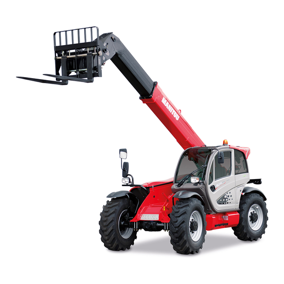
Do you have a question about the MT 835 ST3B and is the answer not in the manual?
Questions and answers