Table of Contents
Advertisement
BP 249
44158 ANCENIS CEDEX - FRANCE
TEL: 33 (0)2 40 09 10 11
YOUR DEALER
547896 EN (17/12/20007)
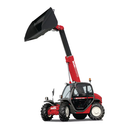
MT 523 Série B-E2
MT 523 MONO-ULTRA Série B-E2
MLT 523 Turbo Série B-E2
MLT 523 Turbo MONO-ULTRA Série B-E2
MT 620 Série B-E2
OPERATOR'S MANUAL
THIS OPERATOR'S MANUAL MUST BE KEPT IN THE LIFT TRUCK AND MUST BE READ AND UNDERSTOOD BY OPERATORS.
Advertisement
Chapters
Table of Contents


Need help?
Do you have a question about the B-E2 Series and is the answer not in the manual?
Questions and answers