
Subscribe to Our Youtube Channel
Related Manuals for Manitou MLT 961-145 V PLUS L JD ST4 S1


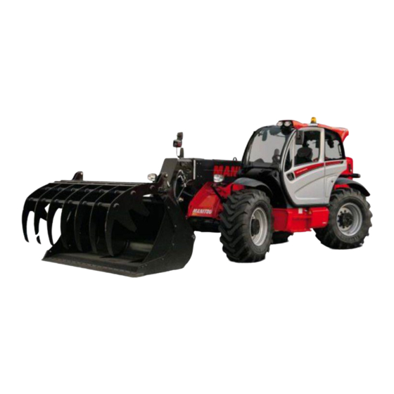
Summary of Contents for Manitou MLT 961-145 V PLUS L JD ST4 S1
- Page 1 649100 EN-US-AU (20/05/2019) MLT 961-145 V PLUS L JD ST4 S1 OPERATOR'S MANUAL (ORIGINAL INSTRUCTIONS)
- Page 2 - Descriptions and figures are non binding. - MANITOU reserves the right to change its models and their equipment without being required to update this manual. - The MANITOU network, consisting exclusively of qualified professionals, is at your disposal to answer all your questions.
- Page 3 MANITOU BF. Any violation of the aforementioned may lead to civil and criminal prosecution. The logos as well as the visual identity of the company are the property of MANITOU BF and may not be...
- Page 4 1 - OPERATING AND SAFETY INSTRUCTIONS 2 - DESCRIPTION 3 - MAINTENANCE 4 - OPTIONAL ATTACHMENTS FOR USE WITH THE RANGE 5 - LOAD CHARTS FOR INTERCHANGEABLE EQUIPMENT...
- Page 5 1 - O P E R A T I N G A N D S A F E T Y INSTRUCTIONS 1 - 1...
- Page 6 1 - 2...
- Page 7 1 - 3...
-
Page 8: Table Of Contents
1 - OPERATING AND SAFETY INSTRUCTIONS INSTRUCTIONS TO THE COMPANY MANAGER THE SITE THE OPERATOR THE TELEHANDLER A - THE TRUCK'S SUITABILITY FOR THE JOB � � � � � � � � � � � � � � � � � � � � � � � � � � � � � � � � � � � � � � � � � � � � 1-6 B - ADAPTATION OF THE TELEHANDLER TO STANDARD ENVIRONMENTAL CONDITIONS �... - Page 9 INSTRUCTIONS FOR USING THE RADIO-CONTROL 1-26 HOW TO USE THE RADIO-CONTROL � � � � � � � � � � � � � � � � � � � � � � � � � � � � � � � � � � � � � � � � � � � � � � � � 1-26 PROTECTIVE DEVICES �...
-
Page 10: Instructions To The Company Manager
A - THE TRUCK'S SUITABILITY FOR THE JOB - MANITOU has ensured that this telehadler is suitable for use under the standard operating conditions defined in this operator's manual, with a STATIC test coefficient of 1.33 and a DYNAMIC test coefficient of 1, as specified in harmonised standard EN 1459 for variable reach trucks�... -
Page 11: C - Modification Of The Telehandler
- The following are some tips for minimizing these vibration doses: • Select the most suitable telehadler and attachment for the intended use� • Adapt the seat adjustment to the operator's weight (according to telehadler model) and maintain it in good condition, as well as the cab suspension�... -
Page 12: Instructions
INSTRUCTIONS - The operator's manual must always be in good condition and kept in the place provided on the telehadler and in the language used by the operator� - The operator's manual and any plates or stickers which are no longer legible or are damaged, must be replaced immediately� MAINTENANCE - Maintenance or repairs other than those detailed in part: 3 - MAINTENANCE must be carried out by qualified personnel your dealer) and under the necessary safety conditions to maintain the health of the operator and any third party�... - Page 13 Page intentionally left blank 1 - 9...
-
Page 14: Instructions For The Operator
- At any time, as an operator, you must envisage, within reason, the possible risk to yourself, to others or to the telehadler itself when you use it� IMPORTANT In order to reduce or avoid any danger with a MANITOU-approved attachment, follow the instructions of paragraph: 4 - ADAPTABLE ATTACHMENTS AVAILABLE ON THE RANGE: INTRODUCTION. GENERAL INSTRUCTIONS A - INSTRUCTION MANUAL - Read the operator's manual carefully�... -
Page 15: E - Lifting People
Right-hand column • With a PLATFORM-fitted telehadler, people can only be lifted using platforms designed by MANITOU for the purpose� - MANITOU sells equipment specifically designed for lifting people (OPTION PLATFORM telehadler, contact your dealer)� OPERATING INSTRUCTIONS UNLADEN AND LADEN... -
Page 16: D - Visibility
- Travelling on a longitudinal slope: • Drive and brake gently� • Moving without load: forks or attachment facing downhill� • Moving with load: Forks or attachment facing uphill� - Take into account the telehadler’s dimensions and its load before trying to negotiate a narrow or low passageway� - Never move onto a loading platform without having first checked: •... -
Page 17: E - Starting The Telehandler
E - STARTING THE TELEHANDLER SAFETY INSTRUCTIONS IMPORTANT The telehadler must only be started up or manoeuvred when the operator is sitting in the driver’s cab, with his seat belt adjusted and fastened. - Never try to start the telehadler by pushing or hauling it� Such an operation may cause severe damage to the transmission� If necessary, towing requires the transmission to be put in neutral ( 3 - MAINTENANCE: OCCASIONAL OPERATION)�... -
Page 18: G - Stopping The Telehandler
- Always remember that hydrostatic type steering is extremely sensitive to movement of the steering wheel, so turn it gently and not jerkily� - Never leave the engine on when the telehadler is unattended� - Do not leave the cab when the telehadler has a raised load� - Look where you are going and always make sure you have good visibility along the route�... -
Page 19: H - Driving The Telehandler On The Public Highway
H - DRIVING THE TELEHANDLER ON THE PUBLIC HIGHWAY (or see current legislation in other countries) FRENCH ROAD TRAFFIC RULES - The driving of non EC type-approved tractors on the public highway is subject to the provisions of the highway code relating to special machines, defined in article R311-1 of the highway code, in category B of the Equipment Order of 20 November 1969 that determines the procedures applicable to special machines�... -
Page 20: Instructions For Handling A Load
INSTRUCTIONS FOR HANDLING A LOAD A - CHOICE OF ATTACHMENTS - Only attachments approved by MANITOU can be used on its telehadlers� - Make sure the attachment is appropriate for the work to be done ( 4 - ADAPTABLE ATTACHMENTS AVAILABLE ON THE RANGE)�... -
Page 21: D - Transverse Attitude Of The Telehandler
D - TRANSVERSE ATTITUDE OF THE TELEHANDLER Depending on the model of telehadler The transverse attitude is the transverse slope of the chassis with respect to the horizontal� Raising the jib reduces the telehadler's lateral stability� The transverse attitude must be set with the jib in down position as follows: 1 - TELEHANDLER WITHOUT ROLL CORRECTOR USED ON TYRES - Position the telehadler so that the bubble in the level is between the two lines (... -
Page 22: F - Taking Up And Setting Down A High Load On Tyres
F - TAKING UP AND SETTING DOWN A HIGH LOAD ON TYRES IMPORTANT You must not raise the jib if you have not checked the transverse attitude of the telehadler ( INSTRUCTIONS FOR HANDLING A LOAD: D - TRANSVERSE ATTITUDE OF THE TELEHANDLER). REMINDER: Make sure that the following operations can be performed with good visibility ( OPERATION INSTRUCTIONS UNLADEN AND LADEN: D... - Page 23 SETTING DOWN A HIGH LOAD ON TYRES - Approach the load in the transport position in front of the stack (fig� F6)� - Apply the parking brake and place the forward/reverse selector in neutral� - Raise and extend the jib (1) (2) until the load is above the stack, while monitoring the longitudinal stability limiter and warning device ( IINSTRUCTIONS FOR HANDLING A LOAD: C - LONGITUDINAL STABILITY LIMITER AND WARNING DEVICE)�...
-
Page 24: G - Taking Up And Setting Down A High Load On Stabilisers
G - TAKING UP AND SETTING DOWN A HIGH LOAD ON STABILISERS Depending on the model of telehadler IMPORTANT You must not raise the jib if you have not checked the transverse attitude of the telehadler ( INSTRUCTIONS FOR HANDLING A LOAD: D - TRANSVERSE ATTITUDE OF THE TELEHANDLER). - Page 25 TAKING UP A HIGH LOAD ON STABILISERS - Ensure that the forks will easily pass under the load� - Check the position of the telehadler with respect to the load and make a test run, if necessary, without taking the load� - Raise and extend the jib (1) (2) until the forks are at the level of the load (fig�...
-
Page 26: H - Picking Up And Setting Down A Suspended Load
H - PICKING UP AND SETTING DOWN A SUSPENDED LOAD IMPORTANT Failure to follow the above instructions may lead the telehadler to lose stability and overturn. MUST be used with a telehadler equipped with an operational hydraulic movement cut-out device. CONDITIONS OF USE - The length of the sling or the chain shall be as short as possible to limit swinging of the load�... -
Page 27: Instructions For Use As A Loader
INSTRUCTIONS FOR USE AS A LOADER For agricultural-type telehadlers (MLT range) A - LOADING IMPORTANT You must not raise the jib if you have not checked the transverse attitude of the telehadler ( INSTRUCTIONS FOR HANDLING A LOAD: D - TRANSVERSE ATTITUDE OF THE TELEHANDLER). -
Page 28: Platform Operating Instructions
B - TELEHANDLER SUITABILITY FOR USE - MANITOU has ensured that this platform is suitable for use under the normal operating conditions defined in this operator's manual, with a STATIC test coefficient of 1.25 and a DYNAMIC test coefficient of 1.1 as specified in harmonised standard EN 280 for "mobile elevating work platforms"�... -
Page 29: F - Maintenance
IMPORTANT It is strictly forbidden to use the platform when the wind speed exceeds 45 km/h (27.9 mph). - To visually recognise this wind speed, refer to the empirical wind evaluation scale below: BEAUFORT scale (wind speed at a height of 10 m on a flat site) Speed Speed Force... - Page 30 INSTRUCTIONS FOR USING THE RADIO-CONTROL For telehadlers with RC radio control HOW TO USE THE RADIO-CONTROL SAFETY INSTRUCTIONS - This radio-control consists of electronic and mechanical safety elements� It cannot receive commands from another transmitter because the internal encoding is unique to each radio-control� IMPORTANT If it is used improperly or incorrectly, there is a risk of danger to: - The physical and mental health of the user or others.
- Page 31 1 - 27...
- Page 32 TELEHANDLER MAINTENANCE INSTRUCTIONS GENERAL INSTRUCTIONS - Ensure the area is sufficiently ventilated before starting the telehadler� - Wear clothes suitable for the maintenance of the telehadler, avoid wearing jewelery and loose clothes� Tie and protect your hair, if necessary� - Stop the engine and remove the ignition key, when an intervention is necessary� - Read the operator's manual carefully�...
- Page 33 LUBRICANT AND FUEL LEVELS - Use the recommended lubricants (never use contaminated lubricants)� - Do not fill the fuel tank when the engine is running� - Only fill up the fuel tank in areas specified for this purpose� - Do not fill the fuel tank to the maximum level� - Do not smoke or approach the telehadler with a flame, when the fuel tank is open or is being filled�...
- Page 34 IF THE TELEHANDLER IS NOT TO BE USED FOR A LONG TIME INTRODUCTION The following recommendations are intended to prevent the telehadler from being damaged when it is withdrawn from service for an extended period� IMPORTANT Procedures to follow if the telehadler is not to be used for a long time and for starting it up again afterwards must be performed by your dealership. This long-term storage period must not exceed 12 months.
- Page 35 BRINGING THE TELEHANDLER BACK INTO SERVICE - Remove the waterproof adhesive tape from all the holes� - Refit and reconnect the battery� - Remove the protection from the cylinder rods� - Carry out daily maintenance ( 3 - MAINTENANCE: 10 HOUR - DAILY MAINTENANCE OR EVERY 10 HOURS OF SERVICE)� - Put the handbrake on and remove the axle stands�...
- Page 36 • Glass items can be removed and collected for processing by glaziers� ENVIRONMENTAL PROTECTION By entrusting the maintenance of your telehadler to the MANITOU network, the risk of pollution is limited and the contribution to environmental protection contribution is made�...
- Page 37 2 – DESCRIPTION 2 - 1...
- Page 38 2 - 2...
- Page 39 INDEX 2 – DESCRIPTION «EC» DECLARATION OF CONFORMITY SAFETY PLATES AND STICKERS IDENTIFICATION OF THE TELEHANDLER TECHNICAL FEATURES FRONT AND REAR TYRES DIMENSIONS LOAD CHART VISIBILITY INSTRUMENTS AND CONTROLS TOWING DEVICES DESCRIPTION AND USE OF OPTIONS 2 - 3...
- Page 40 «EC» DECLARATION OF CONFORMITY DECLARATION "CE" DE CONFORMITE DECLARATION "CE" DE CONFORMITE (originale) (originale) E E E E E E E E E E C C C C C C C C C C " " " " " " " " " " D D D D D D D D D D E E E E E E E E E E C C C C C C C C C C L L L L L L L L L L A A A A A A A A A A R R R R R R R R R R A A A A A A A A A A T T T "...
- Page 41 bg : 1) удостоверение за « СЕ » съответствие (oригинална), 2) Фирмата, 3) Адрес, 4) Техническо досие, 5) Фабрикант на описаната по-долу машина, 6) Обявява, че тази машина, 7) Отговаря на следните директиви и на тяхното съответствие национално право, 8) За машините към допълнение IV, 9)Номер на удостоверението, 10) Наименувана фирма, 15) хармонизирани...
- Page 42 SAFETY PLATES AND STICKERS IMPORTANT Clean all the safety plates and stickers to make them legible. It is essential to replace safety plates and stickers which are illegible or damaged. Check the presence of safety plates and stickers after replacing any spare parts. EXTERNAL PLATES AND STICKERS REFERENCE CODE...
- Page 43 REFERENCE CODE DESCRIPTION 305405 diesel 716907 Flammable liquid hazard 716909 hydraulic oil tank 716908 Diesel fuel 909050 danger of electrocution 307508 battery disconnecting switch 932067 hydraulic oil level point 52514555 hydraulic oil level gauge 52518323 battery maintenance 53017705 rim tightening torque 52563320 fixing points 024653...
- Page 44 PLATES AND STICKERS UNDER THE ENGINE BONNET REFERENCE CODE DESCRIPTION 250707 fan reversal 932095 danger: moving parts 716919 Warning: air intake 52518186 PowerBox fuse plate 288430 repair instructions 716925 Pressurised fluid hazard 716906 danger of hand shearing 52518323 electrical danger 52501046 engine coolant 716905...
- Page 45 PLATES AND STICKERS IN THE CAB REFERENCE CODE DESCRIPTION 297735 Instructions to control the operating mode 290183 bucket on telescopic boom instruction 302780 driver presence / start instructions 184276 steering selection control 52567646 emergency exit 52579106 cabin category 1 Contact your dealer manufacturer's plate 52619895 cab compliance...
- Page 46 IDENTIFICATION OF THE TELEHANDLER As our policy is to promote a constant improvement of our products, our range of telescopic telehandlers may undergo certain modifications, without obligation for us to advise our customers. The following needs to be specified every time you order spare parts or request technical information: NOTE: For the owner's convenience, it is recommended that a note of these numbers is made in the spaces provided at the time of the delivery of the telehandler.
- Page 47 GEARBOX Type Serial No. MANITOU Reference FRONT AXLE Type Serial No. MANITOU Reference REAR AXLE Type Serial No. MANITOU Reference "Manufacturer" "Cabin type" "Serial number" BOOM MANITOU Reference Date of manufacture 2 - 11...
- Page 48 FRAME Serial Number / Product Identification Number ATTACHMENT MANUFACTURER’S PLATE "MODEL" "Serial number" "Year of manufacture" "Unladen weight" "Centre of gravity" "Rated capacity" "Pression service" 2 - 12...
- Page 49 This page is intentionally blank 2 - 13...
- Page 50 TECHNICAL FEATURES I.C. ENGINE Engine JOHN DEERE St.4 (Tier IV) - Type 4045PWL-104 kW - Fuel Diesel - Number of cylinders 4 in-line - Intake Turbocharged - Injection system Direct - Firing order 1.3.4.2 - Displacement 4500 - 4.5 - Bore and stroke mm - in 106 x 127 - 4.17 x 5 - Compression ratio...
- Page 51 Optional front/rear tyres - Type MICHELIN - Size 17.5 - R 25 XHA L3 - Pressure bar - psi 4.5 - 65.26 Optional front/rear tyres - Type NOKIAN - Size 500/70 - R24 TRI STEEL2 - Pressure bar - psi 4 - 58 Optional front/rear tyres - Type...
- Page 52 Maximum operating pressure bar - psi 280 - 4061.06 - Lifting circuit l/min bar 190 - 145 280 - 4061 - Telescopic arm circuit l/min bar 190 - 145 250 - 280/3625.9 - 4061 - Tilting circuit l/min bar 190 - 190 220 - 290/31.90.8 - 4206 - Optional circuit l/min bar...
- Page 53 FRONT AND REAR TYRES LOAD PER TYRE (kg) (ft) PRESSURE FORWARD UNLADEN REVERSE UNLADEN LADEN FRONT LADEN REAR bar (psi) kg (lb) kg (ft) 500/70 - R24 AGRO-IND ALLIANCE RADIAL R-4 (580) (63.81) 500/70 - R24 IND TL MICHELIN 164A8/B XMCL (63.81) 500/70 - R24 164A8/164B TRELLEBORG...
- Page 54 DIMENSIONS 1200 47.24 3000 118.11 1648 64.88 1511 59.49 6106 240.39 5969 235.00 5110 201.18 7306 287.64 1970 77.56 1970 77.56 17.72 17.72 19.29 7° 7° 1459 57.44 39.17 2.36 1891 74.45 7.87 42° 23° 4050 159.45 8654 340.71 4168 164.09 2530 99.61...
- Page 55 LOAD CHART 2 - 19...
- Page 56 VISIBILITY Our telehandlers conform to European standard EN15830 with regard to operator visibility. - Follow the instructions for optimizing operator visibility of the immediate vicinity (e: 1 - OPERATING AND SAFETY INSTRUCTIONS: INSTRUCTIONS TO THE OPERATOR: DRIVING INSTRUCTIONS UNLADEN AND LADEN: D - VISIBILITY). DESCRIPTION AND ADJUSTMENT OF REAR-VIEW MIRRORS 1 - LEFT REAR-VIEW MIRROR 2 - MAIN RIGHT REAR-VIEW MIRROR...
- Page 57 DIRECT AND/OR INDIRECT VISIBILITY BLIND SPOT ZONES In accordance with EN15830, the two diagrams indicate blind spot zones on the visibility test circle (r 12m) and the 1m rectangular zone around the telehandler. HANDLING SUSPENDED LOADS 9,5 m 1 m˜ r 12 m 45°...
- Page 58 INSTRUMENTS AND CONTROLS 29 30 2 - 22...
- Page 59 DESCRIPTION 1 - DRIVER’S SEAT ..............22 2 - SEAT BELT .
-
Page 60: Driver's Seat
1 - DRIVER’S SEAT DRIVER’S SEAT "CLASSIC" FOR GREATER COMFORT, THIS SEAT ALLOWS SEVERAL ADJUSTMENTS. ADJUSTING THE WEIGHT We recommend adjusting the weight with the seat empty. - Refer to notch 1 of the seat. - Turn handle 2 according to the weight of the operator. NOTE: To avoid health problems, we recommend checking and adjusting the weight before starting the lift truck. - Page 61 LONGITUDINAL ADJUSTMENT - Insert the locking lever 5 in the desired position. After it has been locked, it will not allow further movements of the seat. MAINTENANCE IMPORTANT Risks of accident increase when the backseat tilts! Dirt can impair proper operation of the seat. Therefore it must always be kept clean. - To clean or replace the cushions, just pull them out of the frame of the seat.
-
Page 62: Seat Belt
2 - SEAT BELT IMPORTANT In no event should the telehandler be used if the seat belt is defective (fixing, locking, cuts, tears, etc.). Repair or replace the seat belt immediately. - Sit correctly on the seat. - Check that seat belt is not twisted. - Place the seat belt at hip level. -
Page 63: Human-Machine Interface (Hmi)
7 - HUMAN-MACHINE INTERFACE (HMI) 7A - DRIVER PRESENCE 7B - CONTROL PANEL 7C - PANEL FOR BUTTONS AND KEYBOARD 7D - DISPLAY UPDATE: In order to gain maximum advantage from the Man-Machine Interface of your telehandler, contact your dealer to receive the most recent available version of the software. - Page 64 MAJOR FAULT WARNING LIGHT When this light is on it indicates that there is a major fault that may affect the safety for the telehandler or the driver. Stop the telehandler and refer to the error codes (e: 2 – DESCRIPTION: 6D - DISPLAY: MENU SCREEN). GREEN LIGHT FOR LOW BEAM BLUE LIGHT FOR MAIN BEAM AIR FILTER CLOGGING LIGHT...
- Page 65 I.C. ENGINE PREHEATING FAULT INDICATOR LIGHT If the light comes on when the telehandler is running, stop the I.C. engine immediately and look for the cause (possible leak, etc.). NOTE: This light comes on the moment the ignition key is in position I and until the I.C. engine is started. BATTERY LOAD LIGHT If this light comes on when the telehandler is running, switch off the I.C engine immediately and check the electric circuit and the alternator belt.
- Page 66 OPTION BOOM SUSPENSION : 2 – DESCRIPTION: DESCRIPTION AND USE OF OPTIONAL DEVICES. OPTION - ATTACHMENT EASY HYDRAULIC CONNECTION : 2 – DESCRIPTION: DESCRIPTION AND USE OF OPTIONAL DEVICES. OPTION - REAR FOG LIGHT Only works when the low beam or main beam lights are switched on. The indicator will light when in use. OPTION - FRONT WORKING HEADLIGHTS ROTATING BEACON LIGHT NOTE: Except in case of emergency, it is advised to disable the rotating beacon light when the I.C.
- Page 67 Press Cancel 7D - DISPLAY SCREEN OFF Lift truck parked, with ignition off and without the driver. MANITOU LOGO SCREEN System initialising. A beep is sounded when this screen appears. If the screen remains permanently displayed, contact your dealer. DIGIC...
- Page 68 HOUR METER SCREEN With the operator present in the cab and the electrical contact cut, the screen displays the total number of hours worked [888888h], the number of hours for that working day [888.88h] and the number of hours before the next major maintenance [888h].
- Page 69 HELP SCREEN One of these screens appear to inform the operator about the operations to be performed in the current configuration; when this screen is displayed, a buzzer beeps. Maintenance required High soot level in automatic regeneration mode of the exhaust Check (e: 3 - MAINTENANCE: D - EVERY 500 HOURS OF SERVICE).
- Page 70 FAULT SCREEN IMPORTANT In all cases stop the telehandler and contact the dealer. By default, the operation cannot unlock functions (e: 2 – DESCRIPTION: 6D - DISPLAY: MENU SCREEN). One of these screens appears when the system detects a malfunction of the telehandler; when this screen appears, an alarm sounds.
- Page 71 SCR SYSTEM DERATING (checking the emissions of exhaust gas) The DEF and SCR systems of the Final Tier 4 engines must decrease the emis- DTC* LIST sions of NOx generated by the engine. If there are issues of some compo- Faults nents of these systems, the NOx emissions increase, therefore the engine is Fluid level signal in the DEF tank higher than the maximum limit...
- Page 72 Diesel exhaust fluid (DEF) level. The DEF level indicator is proportional and is shown on the display by four segments; each segments equals the DEF level status (approx. 25%, 50%, 75% and 100%). If the DEF level is lower than 10%, a warning is issued and the engine torque decreases by 25%.
- Page 73 INFO FUEL CLOCK > 09:35:51 10/06/2010 MENU SCREEN - Press the button to display the menu screen with the time and date. Navigate horizontally between menus using the buttons and vertically in the sub-menus using the buttons INFO • Time and date (by default). •...
- Page 74 8 - SIGNALLING DEVICE AND LONGITUDINAL STABILITY LIMITER Depending on the model of telehandler IMPORTANT The operator must respect the telehandler's load chart, and the operating mode according to the attachment. This device warns the operator of the telehandler's longitudinal stability limits. However lateral stability may decrease the loading capacity in its top part.
- Page 75 "BUCKET" MODE USE WITH BUCKET SETTING 1 - Place the telehandler in the transport position. - Press the button, "BUCKET" MODE is confirmed by an audible beep and the lighting of the indicator lamp. - Press this button again to return to "HANDLING” MODE. - Protection against forward tip-over when making aggravating movements is ensured, except when the telescopic boom is retracted and/or the telehandler is moving.
- Page 76 A - VISUAL ALARMS • A1 - A2 - A3: the longitudinal stability reserve is significant. • A4 - A5: The telehandler is approaching the limit of longitudinal stability, move with care. • A6: The telehandler is close to the limit for longitudinal stability. Drive carefully. •...
-
Page 77: Switches
9 - SWITCHES BOOM HEAD WORKING HEADLIGHTS (OPTIONAL) FRONT WORKING HEADLIGHTS REAR WORKING LIGHTS UPPER AND REAR WIPER + SPRAY Three-position switch (0, 1a, 1b). This switch identifies the controls that activates the rear and upper wipers (1a) and dispenses the washing liquid (1b) at the same time, starting a wide movement and spraying liquid to clean the windows. - Page 78 EXHAUST PARTICLE FILTER REGENERATION DISABLE AUTOMATIC REGENERATION “STATIONARY TELEHANDLER” REGENERATION MAINTENANCE: I2 - “STATIONARY TELEHANDLER” EXHAUST PARTICLE FILTER) DISABLE AUTOMATIC REGENERATION IMPORTANT Disabling automatic regeneration of the exhaust particle filter is a function that is only to be used in case of necessity (confined or unventilated space, etc.). By default, exhaust particle filter automatic regeneration is enabled each time the telehandler is started.
-
Page 79: Fuses And Relays In The Cab
11 - FUSES AND RELAYS IN THE CAB A sticker on the inside of the access panel provides a quick indication of the use of the fuse plate's components described below. - Remove access door 1 to access the fuses and relays. Replace a used fuse with a new fuse with the same quality and rating. -
Page 80: Fuses And Relays Under The Engine Bonnet
12 - FUSES AND RELAYS UNDER THE ENGINE BONNET - Open engine bonnet 1 in order to gain access to the fuses and relays. Replace a used fuse with a new fuse of the same quality and capacity. Never reuse a repaired fuse. RELAYS •... -
Page 81: Lighting, Horn And Indicator Lights
16 - LIGHTING, HORN AND INDICATOR LIGHTS This lever controls audio and visual signals. • A - Lights are off, turning lights are not operating. • B - Turning lights indicate right. • C - Turning lights indicate left. • D - Position lights and rear lights are on. •... - Page 82 19 - HYDRAULIC CONTROL JOYSTICK According to equipment Authorization for using the hydraulic controls is given by the validation of the driver’s presence (e: 2 – DESCRIPTION: 6 - HUMAN-MACHINE INTERFACE (HMI)) and if the (According to equipment). conditions for using the hydraulic control are followed IMPORTANT Do not attempt to alter the hydraulic system pressure.
-
Page 83: Accelerator Pedal
20 - ACCELERATOR PEDAL Electronic pedal used to change the telehandler speed by acting on the rpm of the I.C. engine. 21 - SERVICE BRAKE PEDAL AND TRANSMISSION CUT-OFF The pedal acts on the front and rear wheels by a power assisted hydraulic brake system, and allows the telehandler to be slowed down and stopped. -
Page 84: Cvt Transmission And Driving Mode Controls
23 - CVT TRANSMISSION AND DRIVING MODE The machine is equipped with a CVT transmission (continuously variable transmission) that ensures the following: • ease of use: speed can be managed between 0 and 40 km/h without changing gear, simply by operating on the accelerator pedal, always maintaining the best available torque to the wheels, •... -
Page 85: I.c. Engine Speed Regulator
- On the contrary, to edit the stored functions: • adjust the maximum speed by means of the speed potentiometer "C"; • increase the engine speed to the desired value and keep pressed the key until the alarm sounds and the screen with the selected settings is displayed, - briefly press the key on the "Button panel and keyboard"... -
Page 86: Heating Vents
26 - HEATER CONTROL A - FAN KNOB This 4-speed control allows the air to be ventilated through the air vents. B - TEMPERATURE ADJUSTMENT KNOB Adjusts the temperature inside the cab. • B1 - The fan pumps in the air at ambient temperature. •... -
Page 87: Door Open Lever
30 - LEVEL INDICATOR Enables the operator to check that the telehandler is in the horizontal position. 31 - DOOR OPEN LEVER 32 - DOOR CLOSE HANDLE 33 - WINDOW REGULATOR SWITCH 34 - SIDE STORAGE SPACE 35 - CEILING LIGHT 36 - HANDLE FOR REAR WINDOW OPENING EMERGENCY EXIT - Use the rear screen as emergency exit if it is not possible to exit from the cab door. -
Page 88: Document Holder Net
39 - DOCUMENT HOLDER NET Make sure that the operator’s manual is in the right place, i.e. in the document holder net. NOTE: An OPTIONAL waterproof document-holder exists. 40 - STORAGE COMPARTMENT 41 - ARMREST ADJUSTMENT The armrest adjustment positions the controller. IMPORTANT Make sure that the armrest’s position is as ergonomic as possible to improve comfortable operation or handling hydraulics. -
Page 89: Emergency Hammer
44 - ROTATING BEACON LIGHT The magnetic rotating beacon light must be clearly visible on the roof of the cab and plugged-in to socket 1. 45 - INSIDE REAR-VIEW MIRROR (OPTION) 46 - BOOM SAFETY LOCK IMPORTANT Only use the wedge supplied with the telehandler. The telehandler is equipped with a boom safety wedge that must be installed on the rod of the lifting cylinder when working beneath the boom (e: 1 - OPERATING AND SAFETY INSTRUCTIONS). - Page 90 The quality of diesel exhaust fluid can be measured with a refractometer, the fluid must be compliant with ISO 22241-1 with a urea solution at 32.5%. MANITOU refractometer reference 959709 STORING DEF (Diesel Exhaust Fluid) Up to 4 months of the lift truck not being used: check the quality of the diesel exhaust fluid with a refractometer.
- Page 91 This page is intentionally blank 2 - 55...
- Page 92 TOWING DEVICES 1 - CHASSIS-MOUNTED FRONT TRAILER HOOK 2 - TOW HOOK 3 - AUTOMATIC TOWING HOOK (OPTIONAL) 4 - TOWING HOOK ON COUPLING LADDER (OPTIONAL) 5 - AUTOMATIC TOWING HOOK ON COUPLING LADDER (OPTIONAL) 6 - AUTOMATIC TOWING JOINT ON COUPLING LADDER (OPTIONAL) 7 - FIXED PIN ON COUPLING LADDER (OPTIONAL) 8 - FIXED TOWING HOOK + HOOK ON COUPLING LADDER (OPTIONAL) 9 - HYDRAULIC TRAILER HOOK (OPTION)
- Page 93 1 - CHASSIS-MOUNTED FRONT TRAILER HOOK IMPORTANT This hook must be used only to tow the telehandler in the event of a fault. 3 - MAINTENANCE: OCCASIONAL OPERATIONS to tow or lift the lift truck. IMPORTANT Pay attention to the risk of pinching or crushing during this operation. Do not forget to put pin back in place.
- Page 94 5 - AUTOMATIC TOWING HOOK ON COUPLING LADDER (OPTIONAL) IMPORTANT Pay attention to the risk of pinching or crushing during this operation. When released, ensure that the trailer stands on its own. - Position the lift truck as near as possible to the trailer ring. ADUSTING THE TOWING HOOK - Lift handle 1 and turn it upward to release pins 2 on each side of the ladder.
- Page 95 7 - FIXED PIN ON COUPLING LADDER (OPTIONAL) IMPORTANT Pay attention to the risk of pinching or crushing during this operation. When released, ensure that the trailer stands on its own. - Position the lift truck as near as possible to the trailer ring. ADUSTING THE TOWING HOOK - Lift handle 1 and turn it upward to release pins 2 on each side of the ladder.
- Page 96 9 - HYDRAULIC TRAILER HOOK (OPTION) IMPORTANT Never use the trailer hook to raise the rear of the lift truck (replacing the rear wheel, for example). IMPORTANT When released, ensure that the trailer stands on its own. - Press switch 4 to position " "...
- Page 97 10 - REAR ELECTRIC SOCKET - Connect the male plug to the female socket 1 on the telehandler and make sure the lights of the trailer or the light bar are working properly. • A - Rear left turning light. •...
-
Page 98: Boom Electrical Fitting
DESCRIPTION AND USE OF OPTIONS Summary 1 - BOOM ELECTRICAL FITTING 2 - ELECTRICAL ADJUSTMENT OF THE MAIN RIGHT REAR VIEW MIRROR 3 - SEMI-AUTOMATIC WHEEL ALIGNMENT 4 - EXTERNAL LOSS RETURN 5 - EASY ATTACHMENT HYDRAULIC CONNECTION (ECS) 6 - FORCED MODE OF THE ATTACHMENT CIRCUIT 7 - BOOM SUSPENSION 8 - ATTACHMENT HYDRAULIC LOCK 9 - BOOM HEAD SOLENOID VALVE... -
Page 99: Electrical Adjustment Of The Main Right Rear View Mirror
2 - ELECTRICAL ADJUSTMENT OF THE MAIN RIGHT REAR VIEW MIRROR Knob 1 identifies the control adjusting the external rear view mirror 2 to improve visibility. Adjusting the external mirror: Turn knob 1 to the appropriate position (arrow 1a on knob as in the image). The external rearview mirror can be adjusted from this position by moving the knob control in the desired direction. -
Page 100: External Loss Return
4 - EXTERNAL LOSS RETURN This allows connecting an attachment for which the loss return is required. • A - Fixed position, drain-back not connected. • B - Movable position, drain-back connected. 5 - EASY ATTACHMENT HYDRAULIC CONNECTION (ECS) This allows easily connecting and disconnecting the attachment hydraulically. OPERATION - Switch on telehandler ignition. -
Page 101: Forced Mode Of The Attachment Circuit
6 - FORCED MODE OF THE ATTACHMENT CIRCUIT IMPORTANT By default, the attachment circuit in continuous mode is disabled as soon as the operator leaves the driver’s cab. This condition can be changed from the OPT menu on the menu screen. ATTACHMENT CIRCUIT UNLOCKED (by default) ATTACHMENT CIRCUIT LOCKED •... -
Page 102: Boom Suspension
7 - BOOM SUSPENSION This reduces shaking of the lift truck on rough ground (e.g. moving straw in a field). The boom suspension is deactivated during the boom lowering, upward tilting or downward tilting movement and is reactivated when the movement ends. Press button to access the various screens shown below. -
Page 103: Boom Head Solenoid Valve
9 - BOOM HEAD SOLENOID VALVE This allows using two hydraulic functions on the attachment circuit. ATTACHMENT LINE L1 CONTROL - Move button 1 forward or backward. ATTACHMENT LINE L2 CONTROL(According to equipment) - Keep pressed button 2 and operate button 1 forward or backward. (According to equipment) 2 - 67... -
Page 104: Boom Head Solenoid Valve + Locking Hydraulic Attachment
10 - BOOM HEAD SOLENOID VALVE + LOCKING HYDRAULIC ATTACHMENT IMPORTANT Once the attachment is locked, return valve 1 to position A to prevent accidental release of the attachment. Adding these two optional devices on the attachment line allows using two hydraulic functions and releasing the attachment on the table. -
Page 105: For Single-Acting Rear Hydraulic Control Fitting
11 - FOR SINGLE-ACTING REAR HYDRAULIC CONTROL FITTING Enables the use of a hydraulic attachment at the rear of the telehandler (e.g. a trailer with hydraulic tipping). SINGLE-ACTING L1 REAR HYDRAULIC CONTROL. - Press the switch 2 (light on) to power the hydraulic control. - Press button 2 forward or backward. -
Page 106: Intelligent Hydraulics
13 - "INTELLIGENT HYDRAULICS" This function allows optimising repeating movement cycles. These hydraulic functions can be combined (e.g. loading material in a truck with tipping bed). "QUICKLIFT" It maximises the cycle time by combining the boom lifting/extension hydraulic movements and the boom descent/withdrawing movements. The load compensation can be adjusted within a horizontal range of ±... -
Page 107: Motor "Eco Stop
15 - MOTOR "ECO STOP" This function allows supporting the I.C. engine stop to limit consumption. This function is possible if all following conditions are met within a time set by the operator. • Rotary I.C. engine. • Speed of the I.C. engine lower than 1000 rpm. •... -
Page 108: Angular Sector On Boom
17 - ANGULAR SECTOR ON BOOM The angular sector displays the boom angle, and thus improves the reading of the load charts. 18 - WINDSCREEN GRILLE DESCRIPTION The windscreen grille provides additional protection for the operator from any external elements spattered on the windscreen. This grille must be removable from inside the cab to enable an emergency exit. - Page 109 3 - MAINTENANCE 3 - 1...
- Page 110 3 - MAINTENANCE MANITOU ORIGINAL SPARE PARTS AND EQUIPMENT LIFT TRUCK MAINTENANCE DAILY AND WEEKLY MAINTENANCE MANDATORY FIRST 500 HOURS OR 6 MONTH SERVICE PERIODIC MAINTENANCE OCCASIONAL MAINTENANCE AND OPERATION FILTER ELEMENTS AND BELTS LUBRICANTS AND FUEL 3-10 Ü 10 HOUR - DAILY MAINTENANCE OR EVERY 10 HOURS OF SERVICE 3-12 Ü...
- Page 111 • Efficient help with diagnostics. • Improvements due to experience feedback. • Operator training. • Only the MANITOU network has a detailed knowledge of the design of the lift truck and therefore the best technical ability to provide maintenance. IMPORTANT ORIGINAL SPARE PARTS ARE DISTRIBUTED EXCLUSIVELY BY MANITOU AND ITS DEALER NETWORK.
- Page 112 This schedule enables the operator to remain up-to-date with the periodic maintenance carried out on the lift truck by notifying the total number of hours of operation completed and the date of the service carried out by the MANITOU network approved professional.
- Page 113 MANDATORY FIRST 500 HOURS OR 6 MONTH SERVICE FIRST 500 HOURS BEFORE THE FIRST 6 MONTHS - If the lift truck completes its first 500 hours of service before the first 6 months are up, carry out the mandatory service and the 500 hour periodic maintenance ( 500 HOUR - PERIODIC MAINTENANCE - EVERY 500 HOURS OF SERVICE) ܌...
- Page 114 PERIODIC MAINTENANCE MAINTENANCE SCHEDULE Þ Þ 1000 H 1500 H 2000 H 500 H Ü EXPIRY FIRST 6 MONTHS FIRST 500 HOURS OR 2 YEARS OR 3 YEARS OR 4 YEARS PERIODIC MAINTENANCE MANDATORY Ü Œ Œ Œ Ž...
- Page 115 Ü 1000 HOUR - PERIODIC MAINTENANCE - EVERY 1000 HOURS OF SERVICE OR 2 YEARS IN ADDITION, CARRY OUT PERIODIC MAINTENANCE FOR 500 HOURS OF SERVICE. - CHECK Seat belt ............... . 3-28 - REGENERATE "Parked telehandler"...
- Page 116 OCCASIONAL MAINTENANCE AND OPERATION Ü OCCASIONAL MAINTENANCE - REPLACE Wheels ................3-40 - ADJUST Front headlights .
- Page 117 FILTER ELEMENTS AND BELTS ܌ 500 HOUR - PERIODIC MAINTENANCE - EVERY 500 HOURS OF SERVICE I.C. ENGINE OIL FILTER CAB INTERNAL VENTILATION FILTER Reference: 796241 Reference: 933871 TRANSMISSION OIL FILTER CAB EXTERNAL VENTILATION FILTER Reference: 737524 Reference: 261971 HYDRAULIC RETURN OIL FILTER CARTRIDGE FUEL FILTER Reference: 52523728 Reference: 282526...
- Page 118 USE THE RECOMMENDED LUBRICANTS AND FUEL: - Not all oils can be mixed to make up the level. - MANITOU oils are perfectly suitable for changing the oil. DIAGNOSTIC ANALYSIS OF OILS If a service or maintenance contract has been organized with the dealer, a diagnostic analysis of engine, transmission and axle oils may be requested depending on the rate of use.
- Page 119 (5.28 US gal) (14.5 US gal) (55.2 US gal) - MANITOUEVOLOGY 10W40 API CJ4 OIL 895837 895838 895839 895840 - MANITOU ISO VG 46 HYDRAULIC OIL 545500 582297 546108 546109 - MANITOU DEXROM III AUTOMATIC TRANSMISSION OIL 947972 947973 947974...
-
Page 120: Hour - Daily Maintenance Or Every 10 Hours Of Service
Ü 10 HOUR - DAILY MAINTENANCE OR EVERY 10 HOURS OF SERVICE CHECK Area around the lift truck Carry out a general inspection of the area surrounding the lift truck: - Any leaks or liquid stains on the ground. - Additional items on the lift truck and in the cab. - Fixing and locking of the attachment. -
Page 121: Check Fuel Pre-Filter
250 hours. IMPORTANT In case of use in abrasive atmospheres (sand, dust, coal), use a protective paint (MANITOU reference: 483536). For more information, contact your dealer. Completely extend the boom. - Apply the grease with a brush ( LUBRICANTS AND FUEL) to the 4 sides of the telescopic booms. -
Page 122: Signalling Device And Longitudinal Stability Limiter
CHECK Signalling device and longitudinal stability limiter IMPORTANT Strictly observe the instructions for positioning the boom. In case of doubt during the test procedure, exit by briefly pressing the cancel button In case of doubts, contact your dealer. TEST Security Test incomplete or failed The appearance of the screen indicates that an instruction, a cancellation request or a late response has not been observed. - Page 123 This page is intentionally blank 3 - 15...
-
Page 124: Hour - Daily Maintenance Or Every 50 Hours Of Service
Ü 50 HOUR - DAILY MAINTENANCE OR EVERY 50 HOURS OF SERVICE CHECK Gearbox oil level Place the lift truck on level ground with boom lifted and the I.C. engine stopped and cool. Check 5 minutes after stopping the I.C. engine. IMPORTANT Raise the boom and place the boom safety wedge on the rod of the lifting cylinder ( 1 - INSTRUCTIONS AND SAFETY RECOMMENDATIONS: LIFT TRUCK MAINTENANCE... -
Page 125: Check Waterproofing On Front Axle Differential
CHECK Waterproofing on front axle differential CHECK Waterproofing on rear axle differential Place the lift truck on level ground with the I.C. engine stopped. - Carry out a visual check of filling, level and drain plugs for any seepage or leaks. - In the event of leaks or seepage, monitor the level: •... -
Page 126: Check Hydraulic Oil Level
CHECK Hydraulic oil level Place the lift truck on level ground with the I.C. engine stopped and the boom retracted and lowered as far as possible. IMPORTANT Use a perfectly clean funnel and clean the top of the oil drum before filling. - Check indicator 1, the level is correct when it is on the red spot. -
Page 127: Clean
CLEAN Radiator grilles IMPORTANT In polluting environments, clean the radiator grille daily. Do not use a high pressure water or steam jet as this could damage the radiator fins. - Open the engine bonnet. - If necessary, clean the suction grille on the engine cover. - Clean grid 1. -
Page 128: Lubricate General Lubrication
LUBRICATE General lubrication To be carried out weekly, if the telehandler has been operated for less than 50 hours during the week. IMPORTANT In the event of prolonged use in an extremely dusty or oxidising atmosphere, reduce this interval to 10 working hours or every day. Clean and lubricate the following points with grease (see: 3 - MAINTENANCE: LUBRICANTS AND FUEL) and remove the surplus of grease. - Page 129 This page is intentionally blank 3 - 21...
- Page 130 CHECK Hydraulic oil MANITOU offers a hydraulic oil analysis kit, which might make it possible to delay the recommended due date for periodic maintenance (2000 hours). In this case we recommend an analysis of the hydraulic oil every 500 hours of operation.
- Page 131 CHECK Automatic tensioner of the alternator belt - Open engine bonnet and the lower cover 1. - Remove the guard 2. ALTERNATOR BELT TENSION - The belt tensioner is designed to work within the travel limits of the boom between the two fixed end-stops 3.
- Page 132 REPLACE Transmission oil filter (hydrostatic pump) - Use a spanner to unscrew the filter body 1 on the transmission pump to replace the cartridge within 2. - Remove cartridge 2. - Clean the mount of the filter and filter body 1 with a wet clean cloth that does not leave lint.
- Page 133 REPLACE Hydraulic return oil filter cartridge Place the telehandler on level ground with the I.C. engine stopped and boom retracted and lowered as far as possible. IMPORTANT Before any intervention, thoroughly clean the area surrounding the drain plugs, the suction strainer and the outside of the filter on the hydraulic tank.
- Page 134 REPLACE Fuel pre-filter IMPORTANT Wipe the outside of the prefilter as well as its support thoroughly to prevent dust from penetrating the system. Make sure the electrical contact on the telehandler is cut, otherwise fuel will be released if the lift pump is on. - Open the engine bonnet.
- Page 135 This page is intentionally blank 3 - 27...
- Page 136 Ü 1000 HOUR - PERIODIC MAINTENANCE - EVERY 1000 HOURS OF SERVICE OR 2 YEARS IN ADDITION, CARRY OUT PERIODIC MAINTENANCE FOR 500 HOURS OF SERVICE. CHECK Seat belt IMPORTANT The lift truck must not be used if the seat belt is defective (fixing, lock, seams, tears, etc.). Repair or replace the seat belt immediately.
- Page 137 CLEAN Fuel tank Place the telehandler on level ground with the I.C. engine stopped. IMPORTANT Do not smoke or use a naked flame during this operation. Never try to perform welding or other operations on your own, taking into account the risk of explosion or fire. - Check by sight and by touch parts where possible leaks of the fuel circuit and tank may occur.
- Page 138 REPLACE Coolant These operations are to be carried out if necessary or every 2 years at the beginning of winter. Place the lift truck on level ground with the I.C. engine stopped and cold. IMPORTANT The I.C. engine does not contain any corrosion resistor and must be filled during the whole year with a mixture containing 25 % of ethylene glycol-based antifreeze.
- Page 139 REPLACE Dry air filter cartridge In case of use in very dusty environments, reduce the cartridge replacement frequency (up to 250 hours in very dusty environments). IMPORTANT Replace the cartridge in a clean environment and with the I.C. engine switched off. Never operate the telehandler without the air filter or with the air filter damaged.
- Page 140 REPLACE Gearbox oil CLEAN Speed sensor IMPORTANT Operation to be carried out the first time after 100 hours of service, periodically every 1000 hours of service. Position the truck on level ground, with the engine switched off and the oil in the gearbox still hot. Place a container under the drainage plug 1 (E11).
- Page 141 CHECK I.C. engine silent blocks * CHECK Gearbox silent blocks * CHECK Gearbox controls * CHECK Brake circuit pressure * CHECK Wear of boom pads * CHECK Condition of wiring harness and cables * CHECK Lighting and signalling * CHECK Indicators * CHECK Side rear-view mirror conditions *...
- Page 142 ÜŽ 2000 HOUR - PERIODIC MAINTENANCE - EVERY 2000 HOURS OF SERVICE OR 4 YEARS IN ADDITION, CARRY OUT PERIODIC MAINTENANCE FOR 500 HOURS OF SERVICE AND 1000 HOURS OF SERVICE. CHECK Tightening torque of the wheel nuts - Check the condition of the tyres, to detect cuts, protuberances, wear, etc. - Check the tightening torque of the wheel nuts with a torque wrench: •...
- Page 143 FILLING UP THE OIL - Refit and tighten the drain plug 2 (tightening torque 29 to 39 N.m). - Fill up with oil (see: 3 - MAINTENANCE: LUBRICANTS AND FUEL) through the filler hole 10. - Observe the oil level on dipstick 11; the oil level should be at the level of the black point. - Check for any possible leaks at the drain plug.
- Page 144 CHECK Radiator * CHECK Transmission pressures * CHECK Steering * CHECK Steering swivel joints * CHECK Wear of the brake pads and the brake disk * CHECK Boom assembly conditions * CHECK Bearings and articulation rings * CHECK Rubber hose pipe and piping conditions CHECK Cylinder conditions (leakage, rods) CHECK...
- Page 145 This page is intentionally blank 3 - 37...
- Page 146 Ü 3000 HOUR - PERIODIC MAINTENANCE - EVERY 3000 HOURS OF SERVICE OR 6 YEARS IN ADDITION, CARRY OUT PERIODIC MAINTENANCE FOR 500 HOURS OF SERVICE AND 1000 HOURS OF SERVICE. REPLACE Dry air filter safety cartridge - To remove and refit the dry air filter cartridge, see: 3 - MAINTENANCE: D3 - DRY AIR FILTER CARTRIDGE.
- Page 147 Ü 4000 HOUR - PERIODIC MAINTENANCE - EVERY 4000 HOURS OF SERVICE OR 8 YEARS IN ADDITION, CARRY OUT PERIODIC MAINTENANCE FOR 500 HOURS OF SERVICE AND 1000 HOURS OF SERVICE. REPLACE DEF (Diesel Exhaust Fluid) feed pump filter Position the telehandler on level ground with the engine stopped.
- Page 148 Ü OCCASIONAL MAINTENANCE REPLACE Wheels For this operation, we recommend using the hydraulic jack MANITOU reference 505507 and the safety support MANITOU reference 554772. IMPORTANT In the event of a wheel being changed on the road, secure the environment of the lift truck: - If possible, stop the lift truck on even and hard ground.
- Page 149 RECALIBRATION Longitudinal stability signalling device According to the use of the telehandler, the device may require to be periodically reset. This procedure simplifies the operation. IMPORTANT Strictly observe the instructions for positioning the boom. GAUGE C a l i b r a t i o n i n c o m p l e t e d The appearance of the screen indicates that an instruction, a cancellation request...
- Page 150 REPLACE Alternator belt - Open engine bonnet and the lower cover 1. - Remove the guard 2. - Place a 1/2" socket wrench in the square of the automatic tensioner 3 to slacken the belt and remove it. - Release the force and remove the socket wrench. - Refit a new alternator belt (see: 3 - MAINTENANCE: FILTER ELEMENTS AND BELTS) ensuring that it is properly seated in the grooves of each pulley and tighten the belt using the automatic tensioner 3.
- Page 151 CLEANING DEF (Diesel Exhaust Fluid) * Contact your dealer IMPORTANT If the “DEF” tank cap is opened at high temperatures, ammonia vapours may escape. Ammonia vapours have a pungent odour and are particularly irritating to - the skin - the mucous membranes - the eyes The presence of such vapours can result in burning eyes, nose, and oral cavities, as well as coughing and tearing.
- Page 152 - Remove the DEF tank* 1. - Inspect the parts of the DEF circuit and the tank liable to leak, both visually and by touch*. - In the event of a leak, contact your dealer.* - Remove from the DEF tank 1: •...
- Page 153 - Pour 2 liters of distilled water 9 in the DEF tank 1 and shake it for at least 1 minute. - For an immediate check on the internal tank cleaning, pour 1 liter of distilled water 9 in the DEF tank 1 and shake it for 30 seconds. - Empty the water through the nylon filter 10 to visually check for the presence of larger or smaller particles.
- Page 154 Ü OCCASIONAL OPERATION TOW OR COUPLE Telehandler IMPORTANT Towing must be done at very low speeds for short distances. - Position the gear selector in neutral position. - Deactivate the parking brake. - Turn on the emergency lights. - Manually shift the travel inverter into neutral. - Activate the bypass function of the hydrostatic pump to allow at the hydraulic oil to flow freely.
- Page 155 HARNESSING Telehandler - Take into account the position of the telehandler center of gravity for lifting. A = 1632 mm (64.2 in) B = 1248 mm (49.1 in) - Place the hooks in the fastening points 1 provided for this purpose.
- Page 156 TRANSPORT Telehandler IMPORTANT Ensure that the safety instructions associated with the platform are complied with before loading the lift truck and that the driver of the carrier vehicle is informed of the dimensions and mass of the lift truck ( 2 - DESCRIPTION: TECHNICAL FEATURES).
- Page 157 4 - OPTIONAL ATTACHMENTS FOR USE WITH THE RANGE...
- Page 159 SUMMARY 4 - OPTIONAL ATTACHMENTS FOR USE WITH THE RANGE INTRODUCTION ATTACHMENT CONNECTION MANOEUVRES ATTACHMENT CHARACTERISTICS...
- Page 161 - Your telehandler must be provided with an interchangeable equipment. This interchangeable equipment is called ATTACHMENT. - A wide range of attachments is available, designed to perfectly adapt to your telehandler and guaranteed by MANITOU. IMPORTANT Only attachments approved by MANITOU can be used with the lift trucks (see: 4 - OPTIONAL ATTACHMENTS FOR USE WITH THE RANGE: ATTACHMENT CHARACTERISTICS).
- Page 162 ATTACHMENT CONNECTION MANOEUVRES 1 - ATTACHMENT WITHOUT HYDRAULIC CIRCUIT WITH MANUAL LOCK ENGAGING THE ATTACHMENT - Check that the attachment is in a position which simplifies the connection to the carriage. If it is badly positioned, take all the necessary precautions to move it safely. - Check that the locking pin is engaged in the support (Fig.
- Page 163 2 - HYDRAULIC ATTACHMENT AND MANUAL LOCK ENGAGING THE ATTACHMENT - Check that the attachment is in a position which simplifies the connection to the carriage. If it is badly positioned, take all the necessary precautions to move it safely. - Check that the locking pin is engaged in the support (Fig.
- Page 164 ATTACHMENT CHARACTERISTICS FLOATING FORK HOLDER TFF 75 MT-1430 REFERENCE 504280 Nominal capacity 8000 kg Width 1545 mm Weight 565 kg FLOATING FORK REFERENCE 528083 578154 Section 200x60x1200 mm 200x60x1500 mm Weight 188 kg 217 kg...
- Page 165 FEM FORK HOLDER PFB FEM4 1200 PFB 75 MT-1750 PFB 75 MT-2000 REFERENCE 732330 504107 527216 Nominal capacity 8000 kg 8000 kg 8000 kg Width 1260 mm 1750 mm 2000 mm Weight 370 kg 460 kg 590 kg FEM FORK HOLDER PFB 75 MT-1750+TDL PFB 75 MT-2000+TDL REFERENCE...
- Page 166 LEVELLING BUCKET CBR 1000 L2500 REFERENCE 744050 Nominal capacity 1000 l Width 2500 mm Weight 693 kg AGRICULTURAL BUCKET CBA 3200 L2500 CBA 4000 L2500 REFERENCE 52000125 52000060 Nominal capacity 3200 l 4000 l Width 2500 mm 2500 mm Weight 1110 kg 1050 kg GRIPPING BUCKET...
- Page 167 GRIPPER FOR BALES PBG 2X4 REFERENCE 757612 Nominal capacity 1000 kg Width 1300 mm Weight 262 kg GRIPPER FOR BALES P2BG 2X4 REFERENCE 790518 Nominal capacity 1500 kg Width 1090 mm Weight 275 kg GRIPPER FOR BALES MBC 2X3 REFERENCE 790506 Nominal capacity 800 kg...
- Page 168 GRABBING FORK FOR MANURE FMG 2450/2000 REFERENCE 790534 Nominal capacity 2000 kg Width 2435 mm Tips Weight FORKS FOR BALES FB 1900/1700 REFERENCE 790699 Nominal capacity 1700 kg Width 1878 mm Tips Weight 215 kg...
- Page 169 BOOM WITH HOOK It MUST be used with a telehandler fitted with hydraulic movement cut-off in service. PCR GM REFERENCE 569548 4000 kg Nominal capacity 260 kg Weight BOOM WITH HOOK It MUST be used with a telehandler fitted with hydraulic movement cut-off in service. PCRB GM 673697 REFERENCE...
- Page 171 - LOAD CHARTS FOR INTERCHANGEABLE EQUIPMENT...
- Page 172 PREAMBLE IMPORTANT The capacity charts are applicable only when the safety system is properly inserted.
- Page 173 MLT 961-145 V PLUS L JD ST4 S1...
- Page 175 MLT 961 104JD ST4 S1...
- Page 176 MLT 961 104JD ST4 S1...
- Page 177 MLT 961 104JD ST4 S1...
- Page 178 MLT 961 104JD ST4 S1...
- Page 179 MLT 961 104JD ST4 S1...
- Page 180 MLT 961 104JD ST4 S1 5-10...
Need help?
Do you have a question about the MLT 961-145 V PLUS L JD ST4 S1 and is the answer not in the manual?
Questions and answers