
Related Manuals for Totem Mini Trooper


Summary of Contents for Totem Mini Trooper
-
Page 2: Mechanical Parts List
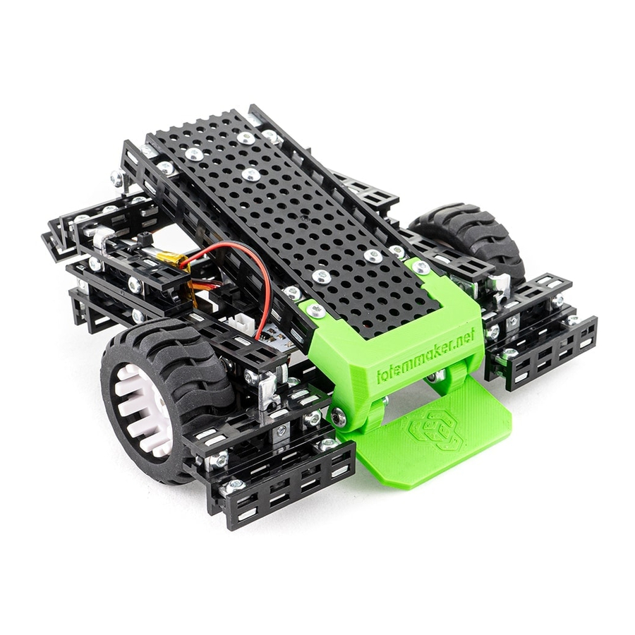
MECHANICAL PARTS LIST 4x Beam 100mm 4x Beam 90mm 10x Beam 40mm 1x Board 30x100mm 4x Bolt M1.6x3 mm 65x Bolt M3x6 mm 12x Bolt M3x8 mm 1x Bolt M3x10 mm 2x Bolt M3x12 mm 2x Bolt M3x16 mm 11x Nut M3 5.5x5.5 mm 65x Nut M3 6x10 mm 6x Lock nut M3 1x Strip bracket 40 mm... - Page 3 ELECTRONICS HOW TO CONTROL? Download Totem app on your smart-phone or Mini Trooper control board — tablet via App Store or Google Play. motor driver board with Bluetooth connectivity. It can control up to 4 DC motors and 2 servo motors. Contains an accelerometer for position sensing.
- Page 4 Correct adjustable brackets’ fixing position 1x Beam 90mm 6x Nut M3 6x10 4x 2-hole simple 6x Bolt M3x6 bracket 2x 2-hole 90 bracket 1x Beam 90mm 6x Nut M3 6x10 4x 2-hole simple 6x Bolt M3x6 bracket 2x 2-hole 90 bracket...
- Page 5 Correct L-twisted Mirror bracket’s fixing position 2x Beam 40mm 5x Nut M3 6x10 2x 2-hole 90 bracket 5x Bolt M3x6 Position 2-hole 90 brackets as shown, so the beams’ edges could align nicely 1x L-twisted mirror bracket Correct L-twisted bracket’s fixing position 2x Beam 40mm 5x Nut M3 6x10...
- Page 6 1x Beam 100 mm 3x Nut M3 6x10 2x Nut M3 5.5x5.5 3x 2-hole simple bracket 2x Standoff 8mm 2x 2-hole 90 bracket 1x Bolt M3x6 mm 2x Bolt M3x8 mm 1x Beam 100 mm 3x Nut M3 6x10 1x 2-hole 90 bracket 1x Bolt M3x6...
- Page 7 2x Beam 40mm 6x Nut M3 6x10 Push the adjustable brackets all the way in as shown 1x Beam 90mm 4x Nut M3 6x10 2x L-twisted bracket 2x L-twisted mirror bracket 4x Bolt M3x6...
- Page 8 Push the adjustable bracket all the way in as shown 1x Beam 100mm 4x Nut M3 6x10 2x 2-hole simple 1x L-twisted bracket bracket 3x Bolt M3x6 Push the adjustable bracket all the way 1x Beam 100mm 4x Nut M3 6x10 in as shown 2x 2-hole simple 1x L-twisted mirror...
- Page 9 1x Flipper part #1 1x Flipper part #2 2x Bolt M3x16 2x Lock nut M3 Tighten the lock nuts just enough to get a smooth “hinge” rotation movement 2x Beam 40mm 3x Nut M3 6x10 1x Bolt M3x12...
- Page 10 M3x8 Push the adjustable bracket all the way in 2x Beam 40mm 4x Nut M3 6x10 as shown 1x L-twisted bracket 1x 3-hole bracket 1x Bolt M3x6 1x Bolt M3x8 M3x6 Step 9 assembly Step 10 assembly 1x Board 30x100mm 4x Nut 5.5x5.5 4x Bolt M3x6...
- Page 11 Step 11 assembly Step 14 assembly 2x Bolt M3x8 Use mini screwdriver for M1.6x3 mm bolts Step 1 assembly 2x Nut 5.5x5.5 1x Mini DC motor 1x Mini DC motor 75:1 bracket ratio 2x Bolt M3x6 2x Bolt 1.6x3...
- Page 12 Use mini screwdriver for M1.6x3 mm bolts Step 2 assembly 2x Nut 5.5x5.5 1x Mini DC motor 1x Mini DC motor 75:1 bracket ratio 2x Bolt M3x6 2x Bolt 1.6x3 Fix assemblies together so the beams’ edges could align nicely. Re-adjust previously mounted brackets’...
- Page 13 Step 13 assembly Step 18 assembly 2x Bolt M3x6 Fix assemblies together so the beams’ edges could align nicely. Re-adjust previously mounted brackets’ positions if needed. Step 19 assembly 1x Mini Servo motor 2x Bolt M3x6 2x Nut M3 6x10 Make sure Servo motor is pressed down...
- Page 14 Step 3 assembly Step 20 assembly 1x Bolt M3x8 1x Nut M3 6x10 Fix assemblies together so the beams’ edges could align nicely. Re-adjust previously mounted L-Twisted Mirror bracket’s position if needed. Step 4 assembly Step 21 assembly 1x Bolt M3x8 1x Nut M3 6x10 Fix assemblies together so the beams’...
- Page 15 Step 7 assembly Step 22 assembly 2x Bolt M3x6 Step 7 assembly Step 23 assembly 2x Bolt M3x6...
- Page 16 Step 8 assembly Step 24 assembly 2x Bolt M3x6 Fix assemblies together so the beams’ edges could align nicely Step 25 assembly 1x Servo arm 1x Servo bolt Turn Servo motor arm counter-clockwise until it reaches dead-zone and it can only be turned to different direction.
- Page 17 Step 12 assembly Step 26 assembly 1x Bolt M3x6 1x Bolt M3x12 Fix assemblies together so the beams’ edges could align nicely. Re-adjust previously mounted brackets’ positions if needed. Step 15 assembly Step 27 assembly 2x Bolt M3x8 2x Lock nut M3 Tighten the lock nuts just enough to get a smooth “hinge”...
- Page 18 Step 28 assembly 1x L-twisted mirror bracket 1x Nut M3 5.5x5.5 1x Bolt M3x6 Tighten the lock nuts just enough to get Step 29 assembly 1x Washer D8 a smooth “hinge” rotation movement 1x Strip bracket 40mm 1x Bolt M3x10 1x Bolt M3x8 2x Lock nut M3...
-
Page 19: Control Board
Step 30 assembly 1x Control board 2x Bolt M3x8 Don’t push down the hood with exces- sive force to close flipper mechanism. Instead of that just rotate the Servo arm. Step 31 assembly 1x Beam 90mm 4x Nut M3 6x10 2x 2-hole 45 bracket 4x Bolt M3x6... - Page 20 Step 32 assembly 2x Ball holder 2x Steel ball D16 4x Nut M3 6x10 4x Bolt M3x6 Step 33 assembly 2x Spacer 5 mm 2x Wheel D-shaft...
- Page 21 CONNECTING ELECTRONICS Light Bar – to indicate the battery charge level. Speaker – makes a sound when successfully connected to the App. Up to 4 DC motor channels.
Need help?
Do you have a question about the Mini Trooper and is the answer not in the manual?
Questions and answers