
Related Manuals for Minarik MM20000A Series


Summary of Contents for Minarik MM20000A Series
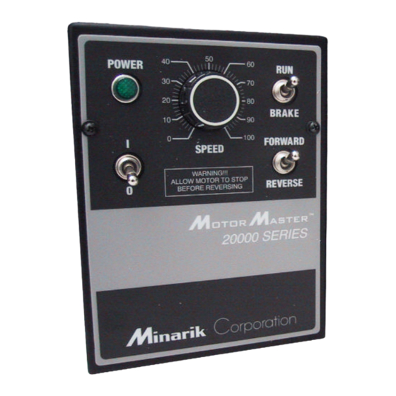
- Page 1 MM20000A MM20000A Series Series Models: MM21111A MM21211A SCR, Adjustable Speed Drives for DC Brush Motors...
- Page 2 Corporation and its Divisions make no warranty of any kind with respect to this material, including, but not limited to, the implied warranties of its merchantability and fitness for a given purpose. Minarik Corporation and its Divisions assume no responsibility for any errors that may appear in this manual and make no commitment to update or to keep current the information in this manual.
- Page 3 Follow sound maintenance procedures. It is possible for a drive to run at full speed as a result of a component failure. Minarik strongly recommends the installation of a master switch in the main power input to stop the drive in an emergency.
-
Page 4: Table Of Contents
Contents Specifications ..........1 Dimensions . - Page 5 FWD-STOP-REV switch ........27 Reversing with dynamic braking .
- Page 6 Illustrations Figure 1. MM21111A Drive Dimensions ....... .2 Figure 2. MM21211A Drive Dimensions .......3 Figure 3.
- Page 7 Table 7. Minarik Filters ........
-
Page 8: Table 1. Mm20000A Series Numbering System
Table 1. MM20000A Series Numbering System MODEL NUMBER M M 2 MotorMaster 20000 Series INPUT VOLTAGE 1 = 115 VAC 2 = 230 VAC 3 = 115/230 VAC (selectable) Voltage Tolerance is ±10%, 50/60 Hz CONFIGURATION 0 = Uncased (Chassis) Drive... -
Page 9: Specifications
Specifications Max. Max. Input Input Armature HP Range Voltage Current Current with 115 VAC Model (AC) (Amps AC) (Amps DC) Applied Style MM21111A 1/20 – 1/8 NEMA 1 MM21211A 1/20 – 1/8 NEMA 1 AC Line Voltage Tolerance ±10%, 50/60 Hz, single phase Armature Voltage 0 –... -
Page 10: Dimensions
Dimensions 6.00 [152] 1.79 [45] 2.50 2.50 [64] [64] 8.00 [203] 5.00 [127] THREE KEYHOLES FOR #10 SCREW ON BACK SIDE FOR MOUNTING 3.46 [88] 2.75 [70] 1.72 2.50 [44] [64] TWO 0.88 [22] CONDUIT HOLES ON BOTTOM SIDE ALL DIMENSIONS IN INCHES [MILLIMETERS] Figure 1. -
Page 11: Figure 2. Mm21211A Drive Dimensions
Dimensions 6.00 [152] 1.79 [45] 2.50 2.50 [64] [64] 8.00 [203] 5.00 [127] THREE KEYHOLES FOR #10 SCREW ON BACK SIDE FOR MOUNTING 3.46 [88] 2.75 [70] 1.72 2.50 [44] [64] TWO 0.88 [22] CONDUIT HOLES ON BOTTOM SIDE ALL DIMENSIONS IN INCHES [MILLIMETERS] Figure 2. -
Page 12: Installation
Installation Drive mounting Warning Do not install, rewire, or remove this control with power applied. Doing so may cause fire or serious injury. Make sure you have read and understood the Safety Warnings on page i before attempting installation. • Drive components are sensitive to electrostatic fields. Avoid direct contact with the circuit board. - Page 13 Installation NEMA 1 cased drives such as the MM21111A and MM21211A come with 0.88 inch (22 mm) conduit holes at the bottom of the case. The units may be vertically wall mounted or horizontally bench mounted using the three keyholes on the back of the case. See Figures 1 and 2 (pages 2 and 3) for mounting hole locations.
-
Page 14: Wiring
Installation Wiring Warning Do not install, remove, or rewire this equipment with power applied. Failure to heed this warning may result in fire, explosion, or serious injury. Circuit potential is at 115 VAC above ground. To prevent the risk of injury or fatality, avoid direct contact with the printed circuit board or with circuit elements. -
Page 15: Shielding Guidelines
As a general rule, Minarik recommends shielding of all conductors. If it is not practical to shield power conductors, Minarik recommends shielding all logic-level leads. If shielding of logic level leads is not practical, the user should twist all logic leads with themselves to minimize induced noise. -
Page 16: Speed Adjust Potentiometer Connections
Installation Speed adjust potentiometer connections MM21111A The speed adjust pot connections on MM21111A drives are configured for unidirectional (one-way) operation. Reversing is accomplished by swapping the A1 and A2 motor armature leads. MM21211A Warning Do not change the FORWARD/REVERSE switch setting while the motor is still running. -
Page 17: Field Output
Installation Field output The field output is for shunt wound motors only. Do not make any connections to F1 and F2 when using a permanent magnet motor. See Table 2 for field output connections. Table 2. Field Output Connections Line Voltage Approximate Connect Motor (VAC) -
Page 18: Line Fusing
Installation Line fusing Minarik drives require an external fuse for protection. Use fast acting fuses rated for 250 VAC or higher, and approximately 150% of the maximum armature current. Fuse blocks are included on MM21111A and MM21211A only. Table 3 lists the recommended line fuse sizes. -
Page 19: Drive Motor Connections
250 volts. Drive motor connections Minarik drives supply motor voltage from A1 and A2 terminals. It is assumed throughout this manual that, when A1 is positive with respect to A2 , the motor will rotate clockwise (CW) while looking at the output shaft protruding from the front of the motor. -
Page 20: Figure 3. Mm21111A And Mm21211A Connections
Installation TB501 FIELD OUTPUT CONNECTIONS NOTE: Do not connect field outputs if using a permanent-magnet motor 90 VDC MOTOR NOT USED 115 VAC INPUT NEUTRAL EARTH GROUND (GREEN SCREW) Figure 3. MM21111A and MM21211A Connections... -
Page 21: Operation
Operation Warning Dangerous voltages exist on the drive when it is powered. BE ALERT. High voltages can cause serious or fatal injury. Before applying power • Verify that no conductive material is present on the printed circuit board. • Verify that the AC supply is properly balanced. MM21111A drive startup and shutdown 1. -
Page 22: Mm21211A Drive Startup And Shutdown
Operation MM21211A drive startup and shutdown 1. Set the RUN/BRAKE switch to the BRAKE position. 2. Set the speed adjust knob to zero speed (full CCW). 3. Set the POWER switch to ON ( | ). 4. Set the FORWARD/REVERSE switch to the desired direction of rotation. -
Page 23: Starting And Stopping Methods
Operation Starting and Stopping Methods Warning NOTE: Minarik strongly recommends the installation of an emergency stop switch. The switch contacts should be rated at a minimum of 125 volts and 200% of maximum motor current. Line starting and stopping When AC line voltage is applied to the drive, the motor accelerates to the set speed. -
Page 24: Dynamic Braking
Operation Dynamic braking Warning Wait for the motor to completely stop before switching it back to RUN. This will prevent high armature currents from damaging the motor or drive. NOTE: For motors rated 1/17 horsepower and lower, a brake resistor is not necessary since the armature resistance is high enough to stop the motor without demagnetization. -
Page 25: Figure 4. Dynamic Brake Connection
Operation Table 4. Recommended Dynamic Brake Resistor Sizes Motor Minimum Minimum Armature Dynamic Brake Dynamic Brake Current Rating Resistor Value Resistor Wattage Less than 2 ADC 1 ohm 2–3 ADC 5 ohm 3–5 ADC 10 ohm 5–10 ADC 20 ohm 10–17 ADC 40 ohm Dynamic... -
Page 26: Calibration
Calibration Warning Dangerous voltages exist on the drive when it is powered. When possible, disconnect the voltage input from the drive before adjusting the trimpots. If the trimpots must be adjusted with power applied, use insulated tools and the appropriate personal protection equipment. BE ALERT. High voltages can cause serious or fatal injury. -
Page 27: Figure 5. Calibration Trimpot Layout
Calibration MOV503 T501 IC502 C502 IC501 C504 INHIBIT ACCEL DECEL MAX SPD MIN SPD TORQUE IR COMP ACCEL MAX SPD TORQUE DECEL MIN SPD IR COMP Figure 5. Calibration Trimpot Layout... -
Page 28: Minimum Speed (Min Spd)
Calibration MINIMUM SPEED (MIN SPD) The MIN SPD setting determines the motor speed when the speed adjust potentiometer is turned full CCW. It is factory set for zero speed. To calibrate, set the MIN SPD trimpot full CCW. Turn the speed adjust potentiometer full CCW. -
Page 29: Torque
Continuous operation beyond this rating may damage the motor. If you intend to operate beyond the rating, contact your Minarik representative for assistance. The TORQUE trimpot setting determines the maximum torque for accelerating and driving the motor. See Figure 6 on page 25... -
Page 30: Ir Compensation (Ir Comp)
Calibration IR COMPENSATION (IR COMP) The IR COMP trimpot setting determines the degree to which motor speed is held constant as the motor load changes. It is factory set for optimum motor regulation. See Figure 6 on page 25 for recommended IR COMP trimpot settings, or recalibrate using the following procedure: 1. -
Page 31: Acceleration (Accel)
Calibration ACCELERATION (ACCEL) The ACCEL setting determines the time the motor takes to ramp to a higher speed. See Specifications on page 1 for approximate acceleration times. ACCEL is factory set for the fastest acceleration time (full CCW). To set the acceleration time: 1. -
Page 32: Deceleration (Decel)
Calibration DECELERATION (DECEL) The DECEL setting determines the time the motor takes to ramp to a lower speed. See Specifications on page 1 for approximate deceleration times. DECEL is factory set for the fastest deceleration time (full CCW). To set the deceleration time: 1. -
Page 33: Figure 6. Typical Ir Comp And Torque Settings
Calibration 1/20 HP 1800 RPM 90 VDC 0.56A CURR IR COMP TORQUE 1/15 HP 1800 RPM 90 VDC 0.75A CURR IR COMP TORQUE 1/8 HP 1800 RPM 90 VDC 1.3A CURR IR COMP TORQUE Figure 6. Typical IR COMP and TORQUE Settings (settings may vary by application) -
Page 34: Application Notes
Application Notes FWD-REV switch Warning Do not change the FORWARD/REVERSE switch setting while the motor is still running. Plug reversing the motor (not allowing the motor to come to a stop before reversing) will cause excessively high currents to flow in the armature circuit, which can damage the control and/or motor. -
Page 35: Fwd-Stop-Rev Switch
Application Notes FWD-STOP-REV switch Warning Do not change the FORWARD/REVERSE switch setting while the motor is still running. Plug reversing the motor (not allowing the motor to come to a stop before reversing) will cause excessively high currents to flow in the armature circuit, which can damage the control and/or motor. -
Page 36: Reversing With Dynamic Braking
Application Notes Reversing with dynamic braking A dynamic brake may be used when reversing the motor direction (Figure 9). Use a three pole, three position switch rated for at least the maximum DC armature voltage and maximum braking current. Wait for the motor to stop completely before switching it to either the forward or reverse direction. -
Page 37: Reversing With A Dlc600
Application Notes Reversing with a DLC600 A DIGI-LOK controller, model DLC600 can be used in a reversing application. The DIGI-LOK must be inhibited while braking. Without the inhibit feature, the DIGI-LOK will continue to regulate. This will cause oversoot when the DIGI-LOK is switched back to the drive. -
Page 38: Independent Adjustable Speeds
Application Notes Independent Adjustable Speeds Connect two speed adjust potentiometers with a single pole two position switch to select between two independent speeds shown in the forward direction (Figure 11). The speed adjust potentiometers can be mounted at two separate operating stations. SPEED 2 SPEED 1 20K OHM... -
Page 39: Adjustable Speeds Using Potentiometers In Series
Application Notes Adjustable speeds using potentiometers in series Replace the speed adjust potentiometer with a single-pole, multi-position switch, and two or more potentiometers in series, with a total series resistance of 10K ohms. Figure 12 shows a connection for fixed high and low speed adjust potentiometers. HIGH 5K OHM SPEED... -
Page 40: Multiple Fixed Speeds
Application Notes Multiple fixed speeds Replace the speed adjust potentiometer with series resistors with a total series resistance of 10K ohms (Figure 13). Add a single pole, multi-position switch with the correct number of positions for the desired number of fixed speeds. Total Series Resistance 10K Ohm... -
Page 41: Run/Jog Switch
Application Notes RUN/JOG switch Using a RUN/JOG switch is recommended in applications where quick stopping is not needed and frequent jogging is required. Use a single pole, two position switch for the RUN/JOG switch, and a single pole, normally closed, momentary operated pushbutton for the JOG pushbutton as shown in Figure 14. -
Page 42: Leader-Follower Application
Application Notes Leader-follower application In this application, use a PCM4 to monitor the speed of the leader motor (Figure 15). The PCM4 isolates the leader motor from the follower drive, and outputs a voltage proportional to the leader motor armature voltage. The follower drive uses this voltage reference to set the speed of the follower motor. -
Page 43: Single Speed Potentiometer Control Of Multiple Drives
Application Notes Single speed potentiometer control of multiple drives Multiple drives can be controlled with a single speed adjust potentiometer using a PCM4 at the input of each drive to provide isolation (Figure 16). Optional ratio potentiometers can be used to scale the PCM4 output voltage, allowing independent control of each drive. -
Page 44: Troubleshooting
5. Verify that there are no short circuits or grounded connections. 6. Check that the drive’s rated armature outputs are consistent with the motor ratings. For additional assistance, contact your local Minarik distributor, or the factory direct: PHONE (800) MINARIK or (800) 646-2745 FAX (800) 394-6334... - Page 45 (page 21). ambient conditions and high-current spikes. 4. Field circuit is shorted. 4. Send in drive to Minarik repair department. Line fuse does not blow, 1. Speed adjust pot or 1. Increase speed adjust but the motor does not run...
- Page 46 Troubleshooting Symptom Possible Suggested Causes Solutions Motor runs too fast at 1. MIN SPD and MAX 1. Recalibrate MIN SPD maximum speed setting SPD settings are too and MAX SPD (page high. 20). 2. Field connections are 2. Check field loose (shunt-wound connections.
-
Page 47: Replacement Parts
Troubleshooting Replacement Parts Replacement parts are available from Minarik Corporation and its distributors for this drive series. Table 5. Replacement Parts ® Model No. Symbol Description Minarik MM21111A D501–503 1N5406 Diode 071-0007 SCR501–502 S8020L High-power SCR 072-0043 R501 0.05 Ohm, 3W Resistor... -
Page 48: Certificate Of Compliance
Certificate of Compliance Minarik Corporation hereby certifies that its MM20000 series drives have been approved to bear the “CE” mark provided the conditions of approval (listed in Exhibit “A”) have been met by the end user. The MM20000 series has been tested to the following test... -
Page 49: Exhibit "A
In addition to EMI/RFI safeguards inherent in the MM20000 series’ design, external filtering is required. Minarik requires the Corcom® filters listed in Table 6. If the exact filter is not available, the specifications are as follows: L = (1.73 + 0.03) milliHenries. -
Page 50: Table 7. Minarik Filters
L & L1 = 2 * (0.8) milliHenries. C & C1 = 2 * (0.1) microFarads @ 400 VDC. R in = 0.1 ohm; R out = 1.2 ohm. Table 7. Minarik Filters Nameplate Current of Motor Wired to the Drive... - Page 51 The end user must use the filtration listed in Exhibit A to comply with CE. The OEM may choose to provide alternative filtering that encompasses the Minarik drive and other electronics within the same panel. The OEM has this liberty because CE is a machinery directive.
- Page 52 Notes...
- Page 53 Notes...
- Page 54 Notes...
-
Page 55: Unconditional Warranty
Unconditional Warranty A. Warranty Minarik Corporation (referred to as "the Corporation") warrants that its products will be free from defects in workmanship and material for twelve (12) months or 3,000 hours, whichever comes first, from date of manufacture thereof. Within this warranty period,... - Page 56 MM23000 Series XP Series (AC or DC Input) 901 East Thompson Avenue Glendale, California 91201-2011 Tel: (800) MINARIK or (800) 646-2745 Fax: (800) 394-6334 www.minarikcorp.com Document Number 250-0077, Revision 3 Printed in the U.S.A – 6/01 $12.00 North America, $13.00 Outside North America...
Need help?
Do you have a question about the MM20000A Series and is the answer not in the manual?
Questions and answers