Table of Contents
Advertisement
Quick Links
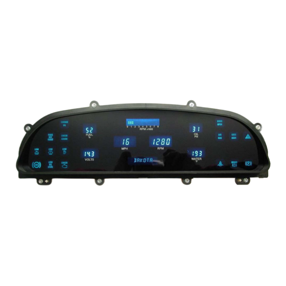
This sheet covers the installation of the Dakota Digital gauge kit into the original cluster.
1. Remove the cluster from the vehicle.
2. Remove the 8 screws holding the clear lens onto
the cluster. Remove clear lens, lens to separator
adapter and separator plate from the gauge cluster. You will not reuse the separator plate.
5. Cut out the divider between the slots on top of the cluster as marked with a red X in the photo on the
left. Remove any sharp points or edges as the ribbon cable for the new gauge system will pass through
here.
6. Pass the ribbon cable through the opening as shown. Feed it through until the display panel is close to
position.
1994-96 Chevy Caprice & 94-95 Impala
Dakota Digital Gauge Installation
3. Remove outer gauges and the gear indicator/speed
display cover.
4. Remove the 4 screws holding in the speed display
board. Also remove the 5 light bulbs in the main
display area.
MAN#650258
Advertisement
Table of Contents

Summary of Contents for Dakota Digital VFD3
- Page 1 1994-96 Chevy Caprice & 94-95 Impala Dakota Digital Gauge Installation This sheet covers the installation of the Dakota Digital gauge kit into the original cluster. 1. Remove the cluster from the vehicle. 2. Remove the 8 screws holding the clear lens onto the cluster.
- Page 2 The stock water temp wire can be spliced into and used but the connector will need to be removed. 4510 W. 61ST St. N.,Sioux Falls, SD 57107 Phone: (605) 332-6513 FAX: (605) 339-4106 www.dakotadigital.com dakotasupport@dakotadigital.com ©Copyright 2009 Dakota Digital Inc. MAN#650258...
- Page 3 The latest in digital dashboard technology for the street rodder, car, and truck enthusiast. INSTALLATION AND OPERATION MANUAL Please read this before beginning installation or wiring. MODELS VFD3 & RET 4510 W. 61ST St. N., Sioux Falls, SD 57107 Phone: (605) 332-6513 FAX: (605) 339-4106 www.dakotadigital.com...
- Page 4 Thank you for purchasing the Vacuum Fluorescent Digital Dashboard from DAKOTA DIGITAL, the leader in custom automotive electronics. Representing the latest electronics dashboard technology for the street rodder, car, and truck enthusiast alike, the digital instrumentation uses state of the art vacuum fluorescent display technology to give the driver up to date and accurate information on the operation of his or her vehicle.
- Page 5 MOUNTING SINGLE LENS SYSTEMS Your DAKOTA DIGITAL single lens system will come to you with a single plexiglass lens and instrumentation that is mounted in an aluminum case. The lens and the instrumentation have corresponding mounting holes. After you have affixed the mounting studs of your choice to the backside of your dash, the lens piece should be slid over the studs followed by the display system.
-
Page 6: Control Box
MOUNTING KITS INTO ORIGINAL DASHES When installing the display system into the original bezel, several steps must be taken to prepare the bezel. The first is to remove the cluster from the dashboard and all instrumentation from the bezel. You should essentially be left with a bare chrome or metal bezel. Remove all felt inserts from the back side of the bezel that sit between the lens and the chrome. - Page 7 The second method allows you to have a dash mounted control to vary the brightness while the headlights are on. This requires a 10k potentiometer or Dakota Digital’s DIM-1 kit. A stock headlight rheostat will not work. The dash mount dimmer has two wires, one connects to the DIM ADJ terminal and the other connects to ground.
- Page 8 The vehicle speed sensor (VSS) connects to this to tell the system how fast the vehicle is moving. For two wire speed sensors, like the one Dakota Digital supplies with this system, the polarity of the wires does not matter. Connect one wire to ground and the other to the speed terminal.
- Page 9 The sending unit should be stamped with “VDO” and “150°C”. Replacement sender part numbers are: Dakota Digital VDO equivalent 1/8” NPT SEN-04-1 323 057 3/8”...
- Page 10 FUEL The fuel gauge sending unit is not normally supplied with the system. The display system will usually use the fuel sending unit that is already in the tank. The sending units that are compatible with this system are as follows: GM, Ford, VDO, and Stewart Warner. It is also possible to program in a custom setting for senders that are not pre-programmed into the system.
- Page 11 The GEAR terminal is used for the gear shift indicator. The indicator is built into every system but it will not light up unless a Dakota Digital GSS-1000/2000/5000 gear shift sending unit is connected to tell it what gear the transmission is in. The gear shift sending unit is not included with the system and must be purchased separately.
-
Page 12: Message Displays
SW 1 or Speed switch The SW 1 terminal is used for selecting the various speed, distance, and performance displays and also for entering the setup menu. The SW 1 input is activated by a ground connection. The push button switch supplied (or any normally open switch) is wired by connecting one terminal to SW 1 and the other terminal to a ground. - Page 13 650066...
- Page 14 GAUGE SYSTEM FEATURES Mileage readings • Million mile odometer • Re-settable trip mileage (0-999.9) • Re-settable service mileage (0-9999) Performance readings • High speed recall. This is reset at power up and can be manually reset. • High rpm recall. This is reset at power up and can be manually reset. •...
-
Page 15: Setup Menu
Setting up the control box SETUP MENU Main Menu Sub Menu DESCRIPTION SPEED AUTO auto calibrate speed ADJUST adjust calibrate speed UNIT select mph F or kph C units MPH F KPH C OUTPUT speed output rate 2K PPM 4K PPM TACH ENGINE set engine cylinder setting... -
Page 16: Speed Calibration
SPEEDOMETER SETUP Press and hold SW 1 switch, then turn the key on and start the engine. Once the engine is running, release the switch. When “SPEED” is displayed, press the switch again and then release it. The message display should switch between “AUTO”, “ADJUST”, “UNIT”, and “OUTPUT”. -
Page 17: Fuel Setup
FUEL SETUP The control box can read 7 different types of preset fuel senders and can also be programmed for a custom fuel sender setup. Press and hold SW 1 switch while turning the key on. Release the switch. When “FUEL” is displayed, press the switch again and then release it. The message display should switch between “SENDER”, “CUSTOM”, and “TEST”. -
Page 18: Tachometer Setup
TACHOMETER SETUP The control box can be set to read from 1-15 cylinder ignition signals. It can also be set to read either 12 volt tach signals or 5 volt tach signals found on some engine computers. The digital tachometer update rate can be adjusted between slow, mid, and fast. The rpm warning/shift point can be adjusted from 2200 –... - Page 19 WATER TEMP SETUP Press and hold SW 1 switch while turning the key on. Release the switch. When “WATER” is displayed, press the switch again and then release it. The message display should switch between “UNIT”, “WARN” and “TEST”. METRIC SELECTION If you are setting the system up for metric displays, press the switch when “UNIT”...
-
Page 20: Warranty
In the event of a problem with one of our products, DAKOTA DIGITAL will replace or repair the instrument at no charge. (The decision to repair or replace is solely that of DAKOTA DIGITAL. DAKOTA DIGITAL is not responsible for shipping costs of products returned under warranty or for labor charges for product installation and removal.) This warranty becomes invalid if the product is... -
Page 21: Troubleshooting Guide
The display panel Return the display panel to light up at all, all others corner of the display is white or Dakota Digital for repair. Include work correctly. the display is cracked or broken a phone number and address. The tachometer will not... - Page 22 Symptom Possible Problem Solution ----------------------------------------------------------------------------------------------------------------------------------- The tachometer reading The tachometer signal wire is Check the connections at both is incorrect. loose or broken. ends of the wire. The engine cylinder setting is Refer to the tach setup section incorrect. of the installation manual. The speedometer will The speed sending unit is not Check that both speed sending...
- Page 23 The sending unit is not Use the sending unit provided compatible with the control box the display system. The sending unit has failed. Return the sending unit to Dakota Digital for replacement. 650066...
- Page 24 Symptom Possible Problem Solution ----------------------------------------------------------------------------------------------------------------------------------- The gear shift indicator The optional gear shift sending Connect the sending unit to the does not light up. unit is not connected to the control box using the control box. instructions supplied with the sending unit.
- Page 25 12 volt power point. (This will keep the correct time.) BLUE connect to the tail light circuit. 4510 W. 61ST St. N., Sioux Falls, SD 57107 Phone: (605) 332-6513 FAX: (605) 339-4106 www.dakotadigital.com dakotasupport@dakotadigital.com ©Copyright 2005 Dakota Digital Inc. 650066...