Advertisement
Quick Links
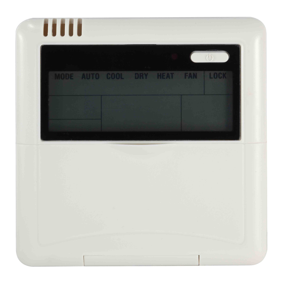
WIRED REMOTE CONTROLLER
Installation Manual
MODEL:
KJR-12B/DP(T)-F(series)
KJR-12B/DP(T)-E(series)
RCW8(P/N:7ACEL1706)
WP-KJR-12B/DP(T)-E-2-02
IMPORTANT NOTE:
Read this manual carefully before
installing or operating your wired
remote controller. Make sure to save
this manual for future reference.
Advertisement

Related Manuals for Midea KJR-12B/DP-F Series


Summary of Contents for Midea KJR-12B/DP-F Series
- Page 1 WIRED REMOTE CONTROLLER Installation Manual MODEL: KJR-12B/DP(T)-F(series) KJR-12B/DP(T)-E(series) RCW8(P/N:7ACEL1706) WP-KJR-12B/DP(T)-E-2-02 IMPORTANT NOTE: Read this manual carefully before installing or operating your wired remote controller. Make sure to save this manual for future reference.
- Page 2 All the pictures in this manual are for explanation purpose only. There may be slightly di erent from wired remote controller you purchased (depend on model). The actual shape shall prevail.
- Page 3 Table of Contents Wall-Mounted Remote Control Wiring......1 Wall-Mounted Remote Control Installation ....6 Constant Air Volume Testing...........13...
- Page 4 Wall-Mounted Remote Control Wiring WARNING The wiring should adapt to the wire control current. • Otherwise, electric leakage or overheating may occur and result in fire. The specified cables shall be used in the wiring. No • external force may be applied to the terminal. Otherwise, the wire may be damaged and heating may occur and result in fire.
- Page 5 An overview of the wall-mounted remote control wire outlet Top side wire outlet Left side Right side wire outlet wire outlet Bottom side wire outlet Fig. 1 1. Wiring diagram Refer to the following diagram to wire the wall-mounted remote control to the indoor unit. Wire Joint, 5p Infrared Pipe 5-Core Shield Cable...
- Page 6 2. Installation Diagram Connect the wire from the display panel of the indoor unit to a connecting cable. Then connect the other side of the connecting cable to the remote control. The connective wires group 5-core wire Front grille shielded wire(some units) Fig.
- Page 7 NOTE:DO NOT allow water to enter the remote control. Use the trap and putty to seal the wires. Putty Trap Putty Putty Trap Trap Fig. 4 a. For exposed mounting, cut holes on four of the sides according to Fig. 5. b.
- Page 8 Cut one hole for wire outlet Fig. 5 Embedded switch box wiring Wiring through the wall Wall hole and wiring hole Wiring hole Diameter of wall hole: Φ 2cm Fig. 6...
- Page 9 Wall-Mounted Remote Control Installation WARNING DO NOT operate the unit with wet hands, as this could lead to electrical shock. Remote Control Dimensions 120mm 21mm 13.1mm (4.7”) (0.8”) (0.5”) 19.5mm (0.7”) 120mm 85.5mm (4.7”) (3.3”) 50mm (1.9”) MODEL A Fig. 7a...
- Page 10 Remote Control Dimensions 120mm 21mm 13.1mm (4.7”) (0.8”) (0.5”) 19.5mm (0.7”) 120mm 85.5mm (4.7”) (3.3”) 50mm (1.9”) MODEL B Fig. 7b...
- Page 11 Preparation Before Installation 1. Ensure you have the following parts Table 1 Name Quantity Remarks Remote Control M4X20 (For mounting on the wall) Screws For mounting on the wall Anchors Screws M4X25 (For mounting on switch box) Plastic screw bars For fixing on switch box The connective Optional...
- Page 12 Installation Method Remove the top panel of remote control Insert a screwdriver into the two slots at the bottom of the remote control to pop o the top panel. Slots Fig. 8 NOTE: The Printed Circuit Board (PCB) is mounted in the upper part of the remote control.
- Page 13 2. Mount the back plate of the remote control For exposed mounting, fasten the back plate to the wall with 3 screws (M4×20) and anchors. Back plate Screws (M4×20) MODEL A Fig. 9a Back plate Screws (M4×20) MODEL B Fig. 9b...
- Page 14 For flush mounting, fasten the back plate to the switch box with 2 screws (M4×25), and fasten the back plate to the wall with 1 screw (M4×20). Switch box Back plate Screw (M4×20) Screws (M4×25) MODEL A Fig. 10a Switch box Back plate Screw (M4×20) Screws (M4×25)
- Page 15 3. Set the time and date The remote control has a small, built-in battery that allows the time and date to be set. That way the remote control can keep time even during a power outage. When the unit displays an incorrect time and date the batteries need to be replaced.
- Page 16 Constant air volume testing (To set external static pressure) (some models) • You can use the unit’s automatic airflow adjustment function to set external static pressure. • Automatic airflow adjustment is the volume of blow-off air that has been automatically adjusted to the quantity rated.
- Page 17 ①When the unit is turned o , hold the MODE button and FAN button down together for three seconds. ("AF" indicator ashes for 3 times.) ②Press “△” or “▽” to select the AF. ③Press “MODE”. The air conditioning unit will then start the fan for air ow automatic adjustment.
- Page 18 Using the wire controller to set air ow rate (some models) When the air conditioning unit is o , perform the follwoing steps: ①Press“MODE” and "FAN" for three seconds. ②Press “△” or “▽” to select the SP. ③Press “MODE” to set the air ow rate in the range of 0~4.
- Page 20 The design and specifications are subject to change without prior notice for product improvement. Consult with the sales agency or manufacturer for details. QSXKQ-001I(12B) 16117100001482 20180112...
- Page 21 此面无需印刷 技术 要求: 1. 双胶纸(说明书)80g非E项目正度 2.尺寸:130*130mm 3.颜色:黑白 4.注意:排版时注意页码数字都是靠外面的,以便翻阅 5.装订。...
Need help?
Do you have a question about the KJR-12B/DP-F Series and is the answer not in the manual?
Questions and answers