
Related Manuals for Macurco CD Series


Summary of Contents for Macurco CD Series
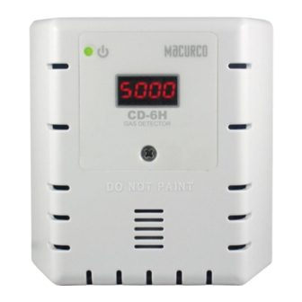
- Page 1 Macurco™ CD-6H/CD-6MC/CD-12H/CD-12MC Carbon Dioxide Detector, Controller and Transducer User Instructions IMPORTANT: Keep these user instructions for reference.
-
Page 2: Table Of Contents
Macurco CD-xx H/MC Manual Table of Contents General Safety Information ................................ 4 List of warnings ................................. 4 Use Instructions and Limitations ..............................5 Use For ....................................5 Do NOT use for .................................. 6 Features ..................................... 6 Specifications ..................................6 2.4.1 6-Series Low Voltage .............................. - Page 3 Auto Test Menu “bUZ” ..............................32 Configuration Menu “CON” ............................. 33 Select Test Menu “tst” ..............................39 CAL Menu *CD-xxMC Only .............................. 40 Macurco Gas Detection Product limited warranty ........................41 Technical Support Contact Information ............................41 General Contact Information ................................41 REV – 1.1...
-
Page 4: General Safety Information
1 General Safety Information The following instructions are intended to serve as a general guideline for the use of the Macurco CD-6H, CD-6MC, CD-12H, and CD-12MC Carbon Dioxide Detector. This manual will refer to these devices a CD-xx-H/MC unless content is specific to a model. -
Page 5: Use Instructions And Limitations
The CD-xxMC has the same setting and features of the CD-xxH with the addition of being able to perform a manual calibration. The CD-xxMC requires a manual calibration process at a minimum of once per year using the Macurco CD6-FCK calibration kit. -
Page 6: Do Not Use For
Macurco CD-xx H/MC Manual 2.2 Do NOT use for The CD-xxH/MC is not intended for use in hazardous locations or industrial applications such as refineries, chemical plants, etc. Do not mount the CD-xxH/MC where the normal ambient temperature is below 32°F or exceeds 122°F (0°C or above 50°C). The CD-xxH/MC mounts on a type 4S electrical box supplied by the contractor. -
Page 7: 6-Series Low Voltage
Macurco CD-xx H/MC Manual 2.4.1 6-Series Low Voltage • Power: 3 W (max) from 12 to 24 VAC or 12 to 32 VDC • Current (max) @ 24 VDC: 126 mA in alarm (two relays), 108 mA (fan relay only) and 85 mA (standby) 2.4.2 12-Series Line Voltage... - Page 8 Macurco CD-xx H/MC Manual 2. Connect the CD-6H/MC to Class 2 power supply only. It is suggested to use a dedicated transformer for powering the unit or units because of possible interferences from other devices on the same power supply.
- Page 9 Macurco CD-xx H/MC Manual Figure 3-2 6-Series Rear View Figure 3-3 6-Series typical installation diagram REV – 1.1 [34-2900-0510-8] P a g e...
- Page 10 Macurco CD-xx H/MC Manual Figure 3-4 6-Series Multiple Device diagram Figure 3-5 6-Series Alarm Control Panel diagram REV – 1.1 [34-2900-0510-8] 10 | P a g e...
- Page 11 Macurco CD-xx H/MC Manual Figure 3-6 6-Series DVP-120 Control Panel Figure 3-7 6-Series Alternate Alarm Panel REV – 1.1 [34-2900-0510-8] 11 | P a g e...
-
Page 12: 12-Series Line Voltage
Macurco CD-xx H/MC Manual Figure 3-8 6-Series Horn & Strobe Combo Wiring 3.2.2 12-Series Line Voltage 1. The CD-12H/MC mounts on a 4” square (or 4x4) electrical box supplied by the contractor. Do not mount the CD- 12H/MC inside another box, unless it has good air flow through it. - Page 13 Macurco CD-xx H/MC Manual Figure 3-9 12-Series 4-20 mA Output diagram Figure 3-10 12-Series Rear View REV – 1.1 [34-2900-0510-8] 13 | P a g e...
- Page 14 Macurco CD-xx H/MC Manual Figure 3-11 12-Series Alarm Control Panel Figure 3-12 12 Series Alarm Control Panel diagram REV – 1.1 [34-2900-0510-8] 14 | P a g e...
- Page 15 Macurco CD-xx H/MC Manual Figure 3-13 12-Series DVP-120 Control Panel Figure 3-14 12-Series Alternate Alarm Panel In this application ( Figure 3-14 12-Series Alternate Alarm Panel ) the Fan or primary relay is used as a low-level alarm relay. The Alarm or secondary relay is used as a supervisory relay when utilized in the normally closed configuration.
-
Page 16: Wiring Connections
Macurco CD-xx H/MC Manual Figure 3-15 12-Series Horn & Strobe Combo Wiring 3.3 Wiring Connections 3.3.1 6-Series Low Voltage With the exception of the safety ground, all field wiring is completed via modular connectors (provided). After wiring, simply plug the modular connectors into the matching connectors on the back side of the detector. -
Page 17: 12-Series Line Voltage
Mains connections should be done in accordance with National and Local Electrical Codes. Only qualified personnel should connect Mains power to any device. Macurco recommends a minimum wire size of AWG18 and the wire insulator must be rated for 140°F (60°C) service. The modular connector will accept wire from 12 to 24 AWG. The safety ground wire should be secured to the ground screw of the metal electrical box. -
Page 18: Operations
Macurco CD-xx H/MC Manual 4 Operations 1. With the display function turned “On”, the CD-xxH/MC will show the current concentration of CO ppm in the air. Normal outdoor concentration ranges between 350-450 ppm. When the CO concentration reaches the Fan Relay setting (2000 ppm, for example) the display will flash back and forth between “FAn”... -
Page 19: 4-20Ma Loop
Macurco CD-xx H/MC Manual 4.4 4-20mA Loop Clean Air – With the 4-20 mA function turned “On” and the current concentration of CO ppm, the 4-20mA loop will output a mA reading equivalent to the current gas reading of the detector. -
Page 20: Selecting Default Configuration - "Def
Macurco CD-xx H/MC Manual Figure 4-1 Board View 4.5.1 Selecting Default Configuration – “dEF” To select the Default Configuration, in normal mode, push the Next button to get to “Con” or the Configuration menu. Then push the Enter button to enter the Con menu. The first selection is the “dEF” or Default setting. Push Enter. If it is already in Default configuration, there will be no action. -
Page 21: Alarm Relay Setting - "Ars
Macurco CD-xx H/MC Manual 4.5.5 Alarm Relay Setting – “ArS” To select the Alarm Relay Setting, in normal mode, push the Next button to get to “Con” or the Configuration menu. Then push the Enter button to enter the Con menu. The fifth selection is the “ArS” or Alarm Relay Setting. Push Next three times to get to “ArS”... -
Page 22: 4-20Ma Output Setting - "420
Macurco CD-xx H/MC Manual 4.5.12 4-20mA Output setting – “420” To select the 4-20mA Output Option, in normal mode, push the Next button to get to “Con” or the Configuration menu. Then push the Enter button to enter the Con menu. The twelfth selection is the “420” or 4-20mA Output Option. Push Next eleven times to get to “420”... -
Page 23: Sensor Poisons
If the error mode repeats frequently, check for continuous power and proper voltage. If power is not the problem and a unit has repeating error conditions, it may need to be returned to Macurco for service, per these User Instructions. -
Page 24: Sensor Life Reset
Check that the green CD-xxH/MC status indicator LED light is illuminated continuously. If not, do not proceed with the tests. If the unit is in error mode, contact your local representative or Macurco technical support representative for information on resolving the problem. -
Page 25: Manual Operation Test
Macurco CD-xx H/MC Manual d. The 4-20mA output will then ramp up from 4 to 16 mA over the next 130 seconds of the test, so if the circuit is wired in the normal manner, the control panel or building automation system should respond. -
Page 26: Field Test Kit
Macurco CD-xx H/MC Manual 7.2.1 Field Test Kit A Field Test Kit, CD6-FTK, is needed to complete a CO gas test. These are available through local distribution. • CD6-FTK: (1) Gas Cylinders (1) 34L 5000 ppm carbon dioxide (CO ) in air •... -
Page 27: Testing The Alarm Relay
Macurco CD-xx H/MC Manual Figure 7-1 Calibration Connection 5. Turn on the regulator to start the gas flow and wait with the gas applied continuously. 6. With the display function turned “On”, the CD-xxH/MC will show the current concentration of CO in the air. -
Page 28: Testing The 4-20Ma Loop
7. Remove the gas from the sensor. Re-assemble the CD-xxH/MC (make sure the LED is aligned with the front case hole). You are done. 7.3.4 Aerosol Test Macurco does not have an Aerosol Option for testing the CD-xxH/MC at this time. 7.4 Field Calibration Procedure 7.4.1 CD-xxH The CD-6H uses an automated background calibration program to set the clean air level on a regular basis. - Page 29 Macurco CD-xx H/MC Manual 14. If the calibration fails, the display will show “CAL6” for 1 second and then change to “Fail.3” for 30 seconds before changing back to CAL for 30 seconds and then displays “t00/t020” Note: this Trouble code will only be cleared by a successful calibration of the sensor.
-
Page 30: Appendix A - Table Of Figures
Macurco CD-xx H/MC Manual 8 Appendix A – Table of Figures Figure 3-1 6-Series 4-20 mA Output diagram ............................. 8 Figure 3-2 6-Series Rear View ................................9 Figure 3-3 6-Series typical installation diagram ..........................9 Figure 3-4 6-Series Multiple Device diagram ............................ 10 Figure 3-5 6-Series Alarm Control Panel diagram .......................... -
Page 31: Appendix B - Menu Structure
Macurco CD-xx H/MC Manual 9 Appendix B – Menu Structure 9.1 Main Menu REV – 1.1 [34-2900-0510-8] 31 | P a g e... -
Page 32: Auto Test Menu "Buz
Macurco CD-xx H/MC Manual 9.2 Auto Test Menu “bUZ” REV – 1.1 [34-2900-0510-8] 32 | P a g e... -
Page 33: Configuration Menu "Con
Macurco CD-xx H/MC Manual 9.3 Configuration Menu “CON” REV – 1.1 [34-2900-0510-8] 33 | P a g e... - Page 34 Macurco CD-xx H/MC Manual REV – 1.1 [34-2900-0510-8] 34 | P a g e...
- Page 35 Macurco CD-xx H/MC Manual REV – 1.1 [34-2900-0510-8] 35 | P a g e...
- Page 36 Macurco CD-xx H/MC Manual REV – 1.1 [34-2900-0510-8] 36 | P a g e...
- Page 37 Macurco CD-xx H/MC Manual REV – 1.1 [34-2900-0510-8] 37 | P a g e...
- Page 38 Macurco CD-xx H/MC Manual REV – 1.1 [34-2900-0510-8] 38 | P a g e...
-
Page 39: Select Test Menu "Tst
Macurco CD-xx H/MC Manual 9.4 Select Test Menu “tst” REV – 1.1 [34-2900-0510-8] 39 | P a g e... -
Page 40: Cal Menu *Cd-Xxmc Only
Macurco CD-xx H/MC Manual 9.5 CAL Menu *CD-xxMC Only REV – 1.1 [34-2900-0510-8] 40 | P a g e... -
Page 41: Macurco Gas Detection Product Limited Warranty
10 Macurco Gas Detection Product limited warranty Macurco warrants the CD-6H / CD-6MC / CD-12H / CD-12MC gas detector will be free from defective materials and workmanship for a period of two (2) years from the date of manufacture (indicated on the inside cover of the CD-6H / CD-6MC), provided it is maintained and used in accordance with Macurco instructions and/or recommendations.
Need help?
Do you have a question about the CD Series and is the answer not in the manual?
Questions and answers