
Related Manuals for Macurco TX-6-ND


Summary of Contents for Macurco TX-6-ND
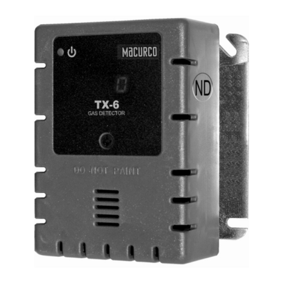
- Page 1 Macurco™ TX-6-ND Nitrogen Dioxide Detector, Controller and Transducer User Instructions Important: Keep these User Instructions for reference...
-
Page 2: Table Of Contents
Fan Minimum Runtime setting Fan Relay Latching setting Trouble Fan Setting 4-20mA Output setting On Board Diagnostics Sensor Poisons MAINTENANCE End-of-Warranty Signal Sensor Replacement Sensor Life Reset Cleaning Testing Operation Test Nitrogen Dioxide Test Field Calibration Procedure MACURCO GAS DETECTION PRODUCTS WARRANTY... -
Page 3: General Safety Information
). The TX-6-ND has selectable 4-20 mA output, buzzer and digital display options. It is an electronic detection system used to measure the concentration of Nitrogen Dioxide and provide feedback and automatic exhaust fan control to help reduce Nitrogen Dioxide concentrations in parking garages, maintenance facilities or other commercial applications. -
Page 4: Use Instructions And Limitations
TX-6-ND where the normal ambient temperature is below 0°F or exceeds 125°F (below -18C or above 52C). The TX-6-ND mounts on a 4x4 electrical box supplied by the contractor. Do not install the TX-6-ND inside another box unless it has good air flow through it. -
Page 5: Features
INSTALLATION AND OPERATING INSTRUCTIONS The following instructions are intended to serve as a guideline for the use of the Macurco TX-6-ND Nitrogen Dioxide Detector. It is not to be considered all-inclusive, nor is it intended to replace the policy and procedures for each facility. If you have any doubts about the... -
Page 6: Location
Location A TX-6-ND is normally mounted at breathing level, about 5 feet (1.5 meters) above the floor on a wall or column in a central area where air movement is generally good. The unit, on average, can cover about 5,000 sq. ft. (465 sq. meters). The coverage depends on air movement within the room or facility. -
Page 7: Garage Diagram
The Fan Relay can be configured for latching or non-latching (default) when activated (when the gas concentration exceeds fan relay set point). Once latched in, power will need to be interrupted or the “TEST” button pressed to un-latch the relay condition. The Fan Relay will engage if the fan setting Nitrogen Dioxide concentration is exceeded for longer than the Fan Relay Delay time. -
Page 10: Alternate Alarm Panel
Power Up The TX-6-ND steps through an internal self-test cycle for the first 1 minute that it is powered. The unit will execute the test cycle any time power is dropped and reapplied (i.e. power failure). During the self-test cycle the unit will display the Firmware Version number and the gas type, then count down from 60 to 0 (if the display option is “on”) and finally go into normal operation. -
Page 11: Display Setting
Selecting Default Configuration – “dEF” To select the Default Configuration, in normal mode, push the Next button to get to “Con” or the Configuration menu. Then push the Enter button to enter the Con menu. The first selection is the “dEF” or Default setting. Push Enter. If it is already in Default configuration, there will be no action. -
Page 12: Alarm Relay Setting
Selecting Alarm Relay Setting – “ArS” To select the Alarm Relay Setting, in normal mode, push the Next button to get to “Con” or the Configuration menu. Then push the Enter button to enter the Con menu. The fifth selection is the “ArS” or Alarm Relay Setting. Push Next four times to get to “ArS” then Enter. -
Page 13: Fan Relay Delay Setting
Onboard Diagnostics The TX-6-ND monitors all critical functions of the unit through software diagnostics that continuously test and verify unit operations. If a problem is found, the unit will switch to a fail-safe/error mode or trouble condition. In this error mode, the Alarm relay will be activated, the 4-20 mA current loop will go to 24 mA, the unit will display the error code, the green status indicator LED light will flash and the buzzer will chirp intermittently. -
Page 14: Sensor Poisons
4. Remove the Shorting Spring from the new sensor and insert the new sensor into the socket. 5. Power up the unit. The TX-6-ND steps through an internal self-test cycle for the first 1 minute that it is powered. During the self-test cycle the unit will display the Firmware Version number, then count down from 60 to 0 and finally go into normal operation. -
Page 15: Sensor Life Reset
Sensor Life Reset 1. Remove the Philips screw on the front of the TX-6-ND. Pull the front cover of the unit off. 2. To reset the sensor life (rSt), from normal or warm-up mode, press the Next button four times to get to SEn or Sensor Mode. -
Page 16: Operation Test
Operation Test Check that the green TX-6-ND status indicator LED light is illuminated continuously. If not, do not proceed with the tests. If the unit is in error mode contact your local representative or Macurco technical service representative for information on resolving the problem. -
Page 17: Nitrogen Dioxide Test
Ensure sensor inlets are unobstructed and is free of debris General The TX-6-ND can be bump-tested or calibrated with the ND-FCK with Nitrogen Dioxide gas, regulator and test hood, available through your local representative or from Macurco. Contents of the FCK ... - Page 18 Turn on the regulator to start the gas flow and wait with the gas applied continuously. With the display function turned “On”, the TX-6-ND will show the current concentration of gas or “0.0” (zero) in clean air. When the gas concentration reaches the Fan Relay setting (1.0 ppm, for example) the display will flash back and forth between “FAn”...
-
Page 19: Field Calibration Procedure
Detector has 4-20 mA option set to “OFF”. Set 4-20mA option to “On” and repeat the test. Remove the gas from the sensor. Re-assemble the TX-6-ND (make sure the LED is aligned with the front case hole). 4-20 current loop test is complete. - Page 20 To return to Normal Mode press Enter and then press Next until “End” is displayed. Press Enter to return to Normal Mode. Calibration Remove the Philips screw on the front of the TX-6-ND. Pull the front cover of the unit off. Assemble the 5 ppm gas cylinder and regulator together.
-
Page 22: Macurco Gas Detection Products Warranty
MACURCO FIXED GAS DETECTION PRODUCTS LIMITED WARRANTY Macurco warrants the TX-6-ND gas detector will be free from defective materials and workmanship for a period of two (2) years from date of manufacture (indicated on the inside cover of the TX-6-ND), provided it is maintained and used in accordance with Macurco instructions and/or recommendations.
Need help?
Do you have a question about the TX-6-ND and is the answer not in the manual?
Questions and answers