Advertisement
Table of Contents
- 1 Table of Contents
- 2 Warning Decal Placement
- 3 Important Precautions
- 4 Before You Begin
- 5 Part Identification Chart
- 6 Assembly
- 7 How to Plug in the Power Cord
- 8 How to Use the Studio Cycle
- 9 How to Use the Console
- 10 Maintenance and Troubleshooting
- 11 Exercise Guidelines
- 12 Part List
- 13 Exploded Drawing
- 14 Ordering Replacement Parts
- 15 Recycling Information
- Download this manual
Model No. NTEVEX16720.0
Serial No.
Write the serial number in the space
above for reference.
Serial Number
CUSTOMER SERVICE
UNITED KINGDOM
Call: 0330 123 1045
From Ireland: 053 92 36102
Website: iconsupport.eu
E-mail: csuk@iconeurope.com
Write:
ICON Health & Fitness, Ltd.
Unit 4, Westgate Court
Silkwood Park
OSSETT
WF5 9TT
UNITED KINGDOM
AUSTRALIA
Call: 1800 993 770
E-mail: australiacc@iconfitness.com
Write:
ICON Health & Fitness
PO Box 635
WINSTON HILLS NSW 2153
AUSTRALIA
CAUTION
Read all precautions and
instructions in this manual before
using this equipment. Keep this
manual for future reference.
Decal
USER'S MANUAL
iconeurope.com
Advertisement
Table of Contents

Related Manuals for NordicTrack S15i


Summary of Contents for NordicTrack S15i
- Page 1 Model No. NTEVEX16720.0 USER’S MANUAL Serial No. Write the serial number in the space above for reference. Serial Number Decal CUSTOMER SERVICE UNITED KINGDOM Call: 0330 123 1045 From Ireland: 053 92 36102 Website: iconsupport.eu E-mail: csuk@iconeurope.com Write: ICON Health & Fitness, Ltd. Unit 4, Westgate Court Silkwood Park OSSETT...
-
Page 2: Table Of Contents
Apply the decal in the location shown. Note: The decal(s) may not be shown at actual size. NORDICTRACK and IFIT are registered trademarks of ICON Health & Fitness, Inc. The Bluetooth word mark ® and logos are registered trademarks of Bluetooth SIG, Inc. and are used under license. Google Maps is a trade- mark of Google LLC. -
Page 3: Important Precautions
IMPORTANT PRECAUTIONS WARNING: To reduce the risk of burns, fire, electric shock, or injury to persons, read all important precautions and instructions in this manual and all warnings on your studio cycle before using your studio cycle. ICON assumes no responsibility for personal injury or property damage sustained by or through the use of this product. - Page 4 15. The studio cycle should not be used by 19. To stop the flywheel quickly, press the brake persons weighing more than 350 lbs. knob downward. (159 kg). 20. When the studio cycle is not in use, press the 16. Be careful when mounting and dismounting brake knob downward and tighten it firmly.
-
Page 5: Before You Begin
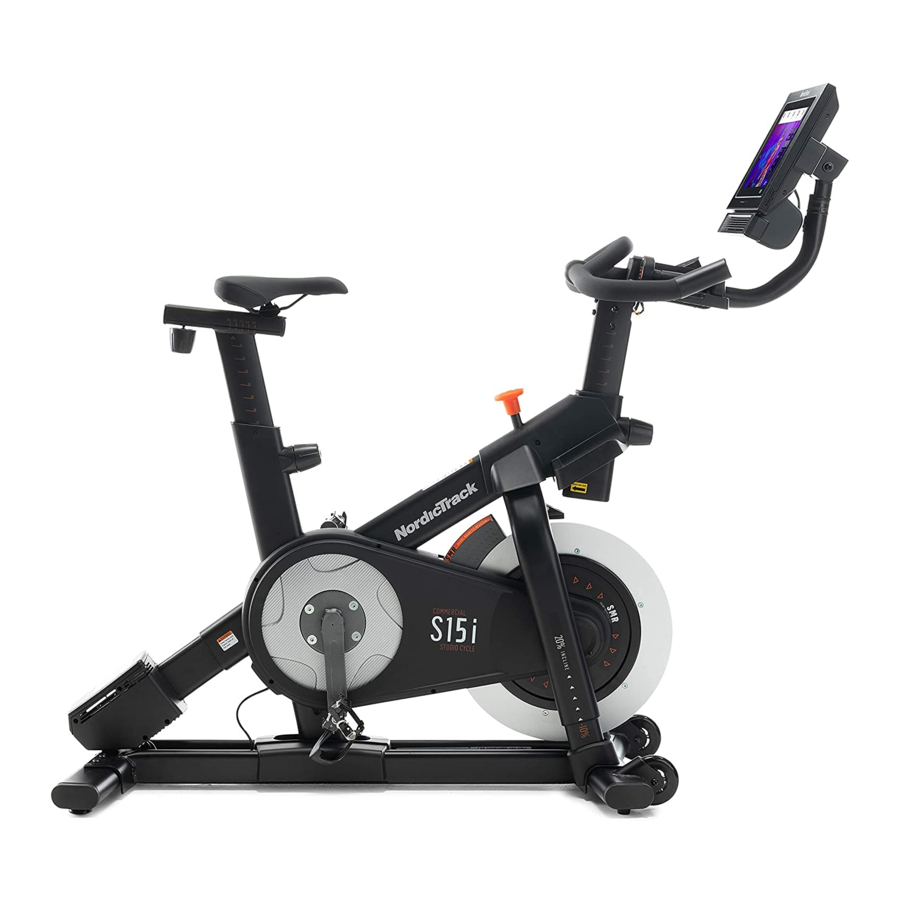
NORDICTRACK COMMERCIAL S15I STUDIO ® CYCLE. The COMMERCIAL S15I STUDIO CYCLE is reading this manual, please see the front cover of this unlike any ordinary exercise bike. With full adjustability, manual. To help us assist you, note the product model an interactive wireless touchscreen console, an incline number and serial number before contacting us. -
Page 6: Part Identification Chart
PART IDENTIFICATION CHART Use the drawings below to identify the small parts needed for assembly. The number in parentheses below each drawing is the key number of the part, from the PART LIST near the end of this manual. The number following the key number is the quantity needed for assembly. -
Page 7: Assembly
ASSEMBLY • Assembly requires two persons. • In addition to the included tool(s), assembly requires the following tool(s): • Place all parts in a cleared area and remove the one Phillips screwdriver packing materials. Do not dispose of the packing materials until you complete all assembly steps. - Page 8 2. Attach the Front Stabilizer (3) to the Base (2) with four M10 x 20mm Screws (105); do not fully tighten the Screws yet. See the inset drawing. Finish attaching the Front Stabilizer (3) with two additional M10 x 20mm Screws (105). Then, fully tighten all six M10 x 20mm Screws (105).
- Page 9 3. Attach the Rear Stabilizer (4) to the Base (2) with four M10 x 20mm Screws (105); do not fully tighten the Screws yet. See the inset drawing. Finish attaching the Rear Stabilizer (4) with two additional M10 x 20mm Screws (105). Then, fully tighten all six M10 x 20mm Screws (105).
- Page 10 5. Insert the Handlebar (97) into the Handlebar Post (7). Attach the Handlebar with four M8 x 12mm Patch Screws (93); start all the Patch Screws, and then tighten them. 6. Tip: Avoid pinching the wires (C). Slide the Console Support (8) onto the Handlebar (97). Attach the Console Support (8) with an M10 x 52mm Bolt (94) and an M10 Jam Nut (95);...
- Page 11 7. Look under the Console Support (8) and identify the Upper Wire (123), which has a larger con- nector than the Extension Wire (124). Connect the Upper Wire (123) to the Lower Wire (122) extending from the Handlebar Post (7). Then, insert the connectors on both Wires into the Handlebar Post.
- Page 12 9. IMPORTANT: Have a second person move the Console (10) to a level position. While the second person holds the Console steady, firmly tighten the M10 x 52mm Bolt (94). Avoid pinching Next, orient the Hand Weight Tray (38) so that the wires (C) the largest opening (E) is facing forward.
- Page 13 11. Note: You can attach your own saddle if desired. See inset drawing a. Tip the Saddle (54) to one side and slide one of the rails (F) as far as possible between the Lower Saddle Clamp (52) and the Upper Saddle Clamp (53). If necessary, further loosen the M8 Saddle Screw (41).
- Page 14 13. Set the two Hand Weights (14) in the Hand Weight Tray (38). IMPORTANT: Make sure not to hit the Console (10) with the Hand Weights (14) when you set the Hand Weights in the Hand Weight Tray (38) after each use. 14.
-
Page 15: How To Plug In The Power Cord
HOW TO PLUG IN THE POWER CORD This product must be earthed. If it should Follow the steps below to plug in the power cord. malfunction or break down, earthing provides a path of least resistance for electric current to reduce the risk 1. -
Page 16: How To Use The Studio Cycle
HOW TO USE THE STUDIO CYCLE FEATURES OF THE STUDIO CYCLE HOW TO ADJUST THE GEOMETRY OF THE STUDIO CYCLE Measuring Watts The studio cycle can be adjusted to match the geom- Each studio cycle is calibrated to measure your power etry of your road bike to promote correct form and to output and to allow you to monitor your watts and ensure proper training of the muscles. - Page 17 How to Adjust the Saddle Post How to Adjust the Position of the Console For effective training, the saddle should be at the The console (E) can proper height. As you pedal, there should be a slight be adjusted upward, bend in your knees when the pedals are in the lowest downward, or to position.
- Page 18 HOW TO USE THE PEDALS HOW TO LOCK THE STUDIO CYCLE To use the pedals, IMPORTANT: Lock the studio cycle insert your shoes when it is not in into the toe cages and pull the ends use. To lock the of the toe straps.
-
Page 19: How To Use The Console
HOW TO USE THE CONSOLE CONSOLE DIAGRAM FEATURES OF THE CONSOLE When you use the manual mode of the console, you can change the resistance of the pedals and the incline The advanced console offers an array of features of the frame with the touch of a button. designed to make your workouts more effective and enjoyable. - Page 20 HOW TO TURN ON THE POWER HOW TO USE THE TOUCH SCREEN IMPORTANT: If the studio cycle has been exposed The console features a tablet with a full-color touch to cold temperatures, allow it to warm to room tem- screen. The following information will help you use the perature before you turn on the power.
- Page 21 HOW TO SET UP THE CONSOLE 5. Check for firmware updates. Before you use the studio cycle for the first time, set up First, touch the menu button (three horizontal lines symbol), touch Settings, touch Maintenance, and the console. then touch Update. The console will check for firm- 1.
- Page 22 HOW TO USE THE MANUAL MODE If desired, adjust the volume level by pressing the volume increase and decrease buttons on the right 1. Touch the screen or press any button on the side of the console. console to turn on the console. To pause the workout, simply touch the screen See HOW TO TURN ON THE POWER on or stop pedaling.
- Page 23 HOW TO USE A FEATURED WORKOUT OR AN To draw your own map for a workout, see HOW TO ONBOARD WORKOUT CREATE A DRAW-YOUR-OWN-MAP WORKOUT on page 25. 1. Touch the screen or press any button on the console to turn on the console. When you select a workout, the screen will show an overview of the workout that includes details See HOW TO TURN ON THE POWER on...
- Page 24 If the resistance level and/or incline level is too high When the workout ends, a workout summary will or too low, you can manually override the setting appear on the screen. If desired, you can select by pressing the Resistance buttons or the Incline/ options such as adding the workout to your sched- Decline buttons.
- Page 25 HOW TO CREATE A DRAW-YOUR-OWN-MAP If you make a mistake, touch Undo in the map WORKOUT options. 1. Touch the screen or press any button on the The screen will display the elevation and distance console to turn on the console. statistics for your workout.
- Page 26 HOW TO USE AN IFIT WORKOUT 4. Select an iFit workout that you have previously added to your schedule on iFit.com. To use an iFit workout, the console must be connected IMPORTANT: Before iFit workouts will load, you to a wireless network (see HOW TO CONNECT TO A must add them to your schedule on iFit.com WIRELESS NETWORK on page 28).
- Page 27 HOW TO CHANGE CONSOLE SETTINGS 3. Customize the unit of measurement and other settings. IMPORTANT: Some of the settings and features described may not be enabled. Occasionally, a To customize the unit of measurement, the time firmware update may cause your console to function zone, or other settings, touch Equipment Info or slightly differently.
- Page 28 6. Calibrate the incline system. 3. Enable Wi-Fi. To calibrate the incline system, touch Maintenance, Make sure that Wi-Fi is enabled. If it is not ® touch Calibrate Incline, and then touch Begin. The enabled, touch the Wi-Fi toggle to enable it. frame will automatically rise to the maximum incline level, lower to the minimum incline level, and then 4.
- Page 29 HOW TO USE THE SOUND SYSTEM THE OPTIONAL CHEST HEART RATE MONITOR To play music or audio books through the console Whether your sound system while you exercise, plug a 3.5 mm male goal is to to 3.5 mm male audio cable (not included) into the burn fat or to jack on the right side of the console and into a jack on strengthen your...
-
Page 30: Maintenance And Troubleshooting
MAINTENANCE AND TROUBLESHOOTING MAINTENANCE If the console does not boot up properly, or if the con- Regular maintenance is important for optimal sole freezes and does not performance and to reduce wear. Inspect and properly respond, reset the console tighten all parts each time the studio cycle is used. to the factory default set- Replace any worn parts immediately. - Page 31 HOW TO ADJUST THE REED SWITCH Then, carefully pull the tops of the Right and Left Shields (30, 32) apart a few inches. If the console does not display correct feedback, the See the inset drawing. Slightly loosen the two indi- reed switch should be adjusted.
- Page 32 HOW TO ADJUST THE DRIVE BELT If the pedals slip while you are pedaling, even when the resistance is adjusted to the highest setting, the drive belt may need to be adjusted. To adjust the drive belt, first unplug the power cord. Then, follow the instructions below.
-
Page 33: Exercise Guidelines
EXERCISE GUIDELINES Aerobic Exercise—If your goal is to strengthen your WARNING: cardiovascular system, you must perform aerobic Before beginning this exercise, which is activity that requires large amounts or any exercise program, consult your physi- of oxygen for prolonged periods of time. For aerobic cian. - Page 34 SUGGESTED STRETCHES The correct form for several basic stretches is shown at the right. Move slowly as you stretch; never bounce. 1. Toe Touch Stretch Stand with your knees bent slightly and slowly bend forward from your hips. Allow your back and shoulders to relax as you reach down toward your toes as far as possible.
- Page 35 NOTES...
-
Page 36: Part List
PART LIST Model No. NTEVEX16720.0 R1219A Key No. Qty. Description Key No. Qty. Description Frame Resistance Disc Base Lower Saddle Clamp Front Stabilizer Upper Saddle Clamp Rear Stabilizer Saddle M6 Shoulder Screw Anchored Zip Tie Pivot Clamp Pedal Set Handlebar Post M4 x 12mm Screw Console Support Upper Leg... - Page 37 Key No. Qty. Description Key No. Qty. Description Carriage Knob M5 x 8mm Screw Upper Brake Bushing M3 x 8mm Screw M4 x 10mm Screw Adjustment Block M10 Clamp Screw M4 x 10mm Blunt Screw M10 x 20mm Screw M3 x 20mm Screw M8 x 85mm Bolt Plastic Spacer M4 x 14mm Machine Screw...
-
Page 38: Exploded Drawing
EXPLODED DRAWING A Model No. NTEVEX16720.0 R1219A... - Page 39 EXPLODED DRAWING B Model No. NTEVEX16720.0 R1219A...
-
Page 40: Ordering Replacement Parts
ORDERING REPLACEMENT PARTS To order replacement parts, please see the front cover of this manual. To help us assist you, be prepared to provide the following information when contacting us: • the model number and serial number of the product (see the front cover of this manual) •...
Need help?
Do you have a question about the S15i and is the answer not in the manual?
Questions and answers
My NordicTrack S1 five by bicycle will not change elevations, I did the calibration, but still does not work
@Paul cataldo s15i
Possible reasons your NordicTrack S15i bike is not changing elevations after calibration include:
- Loose or damaged console connections between the console and main unit.
- Issues with the power supply or outlet.
- Minor system glitches that might require a system reset (unplug for 1–5 minutes and plug back in).
- A need for a full factory reset if basic troubleshooting does not work.
If these steps do not resolve the issue, damaged parts may need inspection and replacement.
This answer is automatically generated
Nordic track s15i will not start
The NordicTrack S15i won’t start despite replacing the power control board. The screen does not turn on, buttons do not respond, and the incline does not calibrate. Possible causes could include a faulty power supply, wiring issues, or a malfunctioning component such as the resistance motor, which may stop receiving power if it moves beyond its position sensing capability. Further troubleshooting of the power connections and control board may be needed.
This answer is automatically generated
emergency shut off key-where does it connect to the S15i cycle