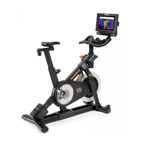
NordicTrack COMMERCIAL S15i STUDIO CYCLE User Manual
Hide thumbs
Also See for COMMERCIAL S15i STUDIO CYCLE:
- User manual ,
- User manual (40 pages) ,
- User manual (40 pages)
Advertisement
Table of Contents
- 1 Table of Contents
- 2 Warning Decal Placement
- 3 Important Precautions
- 4 Before You Begin
- 5 Part Identification Chart
- 6 Assembly
- 7 How to Plug in the Power Cord
- 8 How to Use the Studio Cycle
- 9 How to Use the Console
- 10 Fcc Information
- 11 Maintenance and Troubleshooting
- 12 Exercise Guidelines
- 13 Part List
- 14 Exploded Drawing
- 15 Ordering Replacement Parts
- 16 Limited Warranty
- Download this manual
nordictrack.com
Model No. NTEX05119.6
Serial No.
Write the serial number in the space
above for reference.
Serial Number
ACTIVATE YOUR
WARRANTY
To register your product and
activate your warranty today,
go to my.nordictrack.com.
CUSTOMER CARE
For service at any time, go to
support.nordictrack.com.
Or call 1-800-TO-BE-FIT
(1-800-862-3348)
Mon.–Fri. 6 a.m.–6 p.m. MT
Sat. 8 a.m.–12 p.m. MT
Please do not contact the store.
CAUTION
Read all precautions and
instructions in this manual before
using this equipment. Keep this
manual for future reference.
Decal
USER'S MANUAL
Advertisement
Table of Contents

Related Manuals for NordicTrack COMMERCIAL S15i STUDIO CYCLE


Summary of Contents for NordicTrack COMMERCIAL S15i STUDIO CYCLE
- Page 1 Serial Number Decal ACTIVATE YOUR WARRANTY To register your product and activate your warranty today, go to my.nordictrack.com. CUSTOMER CARE For service at any time, go to support.nordictrack.com. Or call 1-800-TO-BE-FIT (1-800-862-3348) Mon.–Fri. 6 a.m.–6 p.m. MT Sat.
-
Page 2: Table Of Contents
Apply the decal in the location shown. Note: The decal(s) may not be shown at actual size. NORDICTRACK and IFIT are registered trademarks of ICON Health & Fitness, Inc. The Bluetooth word mark ® and logos are registered trademarks of Bluetooth SIG, Inc. and are used under license. Google Maps is a trade- mark of Google LLC. -
Page 3: Important Precautions
IMPORTANT PRECAUTIONS WARNING: To reduce the risk of burns, fire, electric shock, or injury to persons, read all important precautions and instructions in this manual and all warnings on your studio cycle before using your studio cycle. ICON assumes no responsibility for personal injury or property damage sustained by or through the use of this product. - Page 4 15. The studio cycle should not be used by flywheel stops. Reduce your pedaling speed persons weighing more than 350 lbs. in a controlled way. (159 kg). 19. To stop the flywheel quickly, press the brake 16. Be careful when mounting and dismounting knob downward.
- Page 5 STANDARD SERVICE PLANS...
-
Page 6: Before You Begin
If you have questions after NORDICTRACK COMMERCIAL S15I STUDIO ® CYCLE. The COMMERCIAL S15I STUDIO CYCLE is reading this manual, please see the front cover of this unlike any ordinary exercise bike. manual. To help us assist you, note the product model number and serial number before contacting us. -
Page 7: Part Identification Chart
PART IDENTIFICATION CHART Use the drawings below to identify the small parts needed for assembly. The number in parentheses below each drawing is the key number of the part, from the PART LIST near the end of this manual. The number following the key number is the quantity needed for assembly. -
Page 8: Assembly
• To avoid damaging parts, do not use power tools. Assembly may be easier if you have a set of wrenches. 1. Go to my.nordictrack.com on your computer and register your product. • documents your ownership • activates your warranty •... - Page 9 2. Attach the Front Stabilizer (3) to the Base (2) with four M10 x 20mm Screws (105); do not fully tighten the Screws yet. See the inset drawing. Finish attaching the Front Stabilizer (3) with two additional M10 x 20mm Screws (105). Then, fully tighten all six M10 x 20mm Screws (105).
- Page 10 3. Attach the Rear Stabilizer (4) to the Base (2) with four M10 x 20mm Screws (105); do not fully tighten the Screws yet. See the inset drawing. Finish attaching the Rear Stabilizer (4) with two additional M10 x 20mm Screws (105). Then, fully tighten all six M10 x 20mm Screws (105).
- Page 11 5. Insert the Handlebar (97) into the Handlebar Post (7). Attach the Handlebar with four M8 x 12mm Patch Screws (93); start all the Patch Screws, and then tighten them. 6. Tip: Avoid pinching the wires (C). Slide the Console Support (8) onto the Handlebar (97). Attach the Console Support (8) with an M10 x 55mm Bolt (94) and an M10 Locknut (135);...
- Page 12 7. Look under the Console Support (8) and iden- tify the Upper Wire (123), which has a larger connector than the Extension Wire (124). Connect the Upper Wire (123) to the Lower Wire (122) extending from the Handlebar Post (7). Then, insert the connectors on both Wires into the Handlebar Post.
- Page 13 9. IMPORTANT: Have a second person move the Console (10) from side to side, if necessary, so that it is level. While the second person Avoid holds the Console still, firmly tighten the pinching M10 x 55mm Bolt (94). the wires Next, orient the Hand Weight Tray (38) so that the largest opening (E) is facing forward.
- Page 14 11. Note: You can attach your own saddle if desired. See inset drawing a. Tip the Saddle (54) to one side and slide one of the rails (F) as far as possible between the Lower Saddle Clamp (52) and the Upper Saddle Clamp (53). If necessary, further loosen the M8 Saddle Screw (41).
- Page 15 13. Set the two Hand Weights (14) in the Hand Weight Tray (38). IMPORTANT: Make sure not to hit the Console (10) with the Hand Weights (14) when you set the Hand Weights in the Hand Weight Tray (38) after each use. 14.
-
Page 16: How To Plug In The Power Cord
HOW TO PLUG IN THE POWER CORD This product must be grounded. If it should mal- A temporary function or break down, grounding provides a path of adapter (C) may least resistance for electric current to reduce the risk be used to con- of electric shock. -
Page 17: How To Use The Studio Cycle
HOW TO USE THE STUDIO CYCLE FEATURES OF THE STUDIO CYCLE HOW TO ADJUST THE GEOMETRY OF THE STUDIO CYCLE Measuring Watts The studio cycle can be adjusted to match the geom- Each studio cycle is calibrated to measure your power etry of your road bike to promote correct form and to ensure proper training of the muscles. - Page 18 How to Adjust the Saddle Post HOW TO LEVEL THE STUDIO CYCLE For effective training, the saddle should be at the If the studio cycle proper height. As you pedal, there should be a slight rocks slightly on bend in your knees when the pedals are in the lowest your floor during position.
-
Page 19: How To Use The Console
HOW TO USE THE CONSOLE CONSOLE DIAGRAM FEATURES OF THE CONSOLE When you use the manual mode of the console, you can change the resistance of the pedals and the incline The advanced console offers an array of features of the frame with the touch of a button. designed to make your workouts more effective and enjoyable. - Page 20 HOW TO TURN ON THE POWER HOW TO USE THE TOUCH SCREEN IMPORTANT: If the studio cycle has been exposed The console features a tablet with a full-color touch to cold temperatures, allow it to warm to room tem- screen. The following information will help you use the perature before you turn on the power.
- Page 21 HOW TO SET UP THE CONSOLE 5. Check for firmware updates. Before you use the studio cycle for the first time, set up First, touch the menu button (three horizontal lines symbol), touch Settings, touch Maintenance, and the console. then touch Update. The console will check for firm- 1.
- Page 22 HOW TO USE THE MANUAL MODE Drag upward on the screen to enter the fullscreen display mode. Drag downward on the screen to 1. Touch the screen or press any button on the view the workout information displays. console to turn on the console. Touch the various workout information displays See HOW TO TURN ON THE POWER on to view more options.
- Page 23 6. Turn on the fan if desired. 3. Select a workout. The fan has several speed settings, To select a workout from the main menu or the including an auto mode. While the workout library, simply touch the desired workout auto mode is selected, the speed of button on the screen.
- Page 24 During some workouts, the screen may show a To pause the workout, simply touch the screen target speed. As you exercise, keep your pedaling or stop pedaling. To continue the workout, simply speed near the target speed shown on the screen. resume pedaling.
- Page 25 HOW TO CREATE A DRAW-YOUR-OWN-MAP If you make a mistake, touch Undo in the map WORKOUT options. 1. Touch the screen or press any button on the The screen will display the elevation and distance console to turn on the console. statistics for your workout.
- Page 26 HOW TO USE AN IFIT WORKOUT Manage Accounts. If more than one user is associ- ated with the account, a list of users will appear. To use an iFit workout, the console must be connected Touch the name of the desired user. to a wireless network (see HOW TO CONNECT TO A 4.
- Page 27 HOW TO CHANGE CONSOLE SETTINGS 3. Customize workout settings. IMPORTANT: Some of the settings and features To customize workout settings, touch In Workout, described may not be enabled. Occasionally, a and then touch the desired settings. It is firmware update may cause your console to function recommended that you enable the option to show slightly differently.
- Page 28 7. Calibrate the incline system. 3. Enable Wi-Fi. To calibrate the incline system, touch Maintenance, Make sure that Wi-Fi is enabled. If it is not ® touch Calibrate Incline, and then touch Begin. The enabled, touch the Wi-Fi toggle to enable it. frame will automatically rise to the maximum incline level, lower to the minimum incline level, and then 4.
- Page 29 HOW TO USE THE SOUND SYSTEM Connect Your Headphones If the console has a headphones jack, you can plug Connect with an Audio Cable your headphones into the headphones jack to listen to To play music or audio books through the console audio from the console through your headphones.
-
Page 30: Fcc Information
FCC INFORMATION This equipment has been tested and found to comply with the limits for a Class B digital device, pursuant to part 15 of the FCC Rules. These limits are designed to provide reasonable protection against harmful interference in a residential installation. This equipment generates, uses, and can radiate radio frequency energy and, if not installed and used in accordance with the instructions, may cause harmful interference to radio communications. -
Page 31: Maintenance And Troubleshooting
MAINTENANCE AND TROUBLESHOOTING MAINTENANCE If the console does not boot up properly, or if Regular maintenance is important for optimal the console freezes and performance and to reduce wear. Inspect and properly does not respond, reset tighten all parts each time the studio cycle is used. the console to the fac- Replace any worn parts immediately. - Page 32 HOW TO ADJUST THE LEFT CRANK ARM If the Left Crank Arm (21) feels loose while you are pedaling, tighten the two M6 x 25mm Screws (96). Note: If you have a torque wrench, tighten one Screw to 20 Nm (14.75 ft-lbs.), tighten the second Screw to 20 Nm, and then tighten each Screw a second time to 20 Nm.
- Page 33 HOW TO ADJUST THE DRIVE BELT If the pedals slip while you are pedaling, even when the resistance is adjusted to the highest setting, the drive belt may need to be adjusted. To adjust the drive belt, first unplug the power cord. Then, follow the instructions below.
-
Page 34: Exercise Guidelines
EXERCISE GUIDELINES Aerobic Exercise—If your goal is to strengthen your WARNING: cardiovascular system, you must perform aerobic Before beginning this exercise, which is activity that requires large amounts or any exercise program, consult your physi- of oxygen for prolonged periods of time. For aerobic cian. - Page 35 SUGGESTED STRETCHES The correct form for several basic stretches is shown at the right. Move slowly as you stretch; never bounce. 1. Toe Touch Stretch Stand with your knees bent slightly and slowly bend forward from your hips. Allow your back and shoulders to relax as you reach down toward your toes as far as possible.
-
Page 36: Part List
PART LIST Model No. NTEX05119.6 R0320B Key No. Qty. Description Key No. Qty. Description Frame Resistance Disc Base Lower Saddle Clamp Front Stabilizer Upper Saddle Clamp Rear Stabilizer Saddle M6 Shoulder Screw Anchored Zip Tie Inner Leg Sleeve Pedal Set Handlebar Post #8 x 1/2"... - Page 37 Key No. Qty. Description Key No. Qty. Description Carriage Knob M8 Large Washer M4 Set Screw M5 Nut M4 x 10mm Screw M5 x 8mm Screw Incline Motor Sleeve #6 x 5/8" Screw M10 x 20mm Screw Adjustment Block M8 x 83mm Bolt M4 x 10mm Blunt Screw M4 x 15mm Machine Screw Shoe Pin...
-
Page 38: Exploded Drawing
EXPLODED DRAWING A Model No. NTEX05119.6 R0320B... - Page 39 EXPLODED DRAWING B Model No. NTEX05119.6 R0320B...
-
Page 40: Ordering Replacement Parts
ORDERING REPLACEMENT PARTS To order replacement parts, please see the front cover of this manual. To help us assist you, be prepared to provide the following information when contacting us: • the model number and serial number of the product (see the front cover of this manual) •...
Need help?
Do you have a question about the COMMERCIAL S15i STUDIO CYCLE and is the answer not in the manual?
Questions and answers
Won't come on
Possible reasons for the NordicTrack S15i Studio Cycle not turning on include:
1. Exterior wires are not connected correctly or firmly.
2. Power switch on the console is not turned on.
3. Connectors are misaligned or loose.
4. Console needs to be restarted by turning the power switch off and then on again.
5. The console may take a few minutes to be ready after powering on.
6. The power cord may not be properly grounded or connected.
7. The plug may not fit the outlet, or the outlet is not properly grounded.
Check all connections and grounding before retrying.
This answer is automatically generated