Advertisement
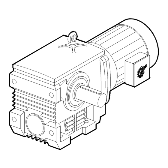
UNICASE
Installation and Maintenance Instructions
Thoroughly inspect the equipment for any shipping and handling damage before accepting shipment from the freight company. If any of the
goods called for in the bill of lading or express receipt are damaged or the quantity is short, do not accept until the freight or express agent
makes an appropriate notation on your freight bill or express receipt. If any concealed loss or damage is discovered later, notify your freight
carrier or express agent at once and request him to make an inspection. We will be very happy to assist you in collecting claims for loss or
damage during shipment; however, this willingness on our part does not remove the transportation company's responsibility in reimbursing
you for collection of claims or replacement of material. Claims for loss or damage in shipment must not be deducted from the NORD Gear
invoice, nor should payment of the NORD Gear invoice be withheld awaiting adjustment of such claims, as the carrier guarantees safe
delivery.
If considerable damage has been incurred and the situation is urgent, contact the nearest NORD Gear Sales Office for assistance. Please
keep a written record of all communications.
Locate the gear reducer nameplate and record all nameplate data for future reference.
SK ________________________________________________________ S/N _________________________________
RATIO ______________ MAX TORQUE ____________________ RPM ______________ MTG. POS ______________
PROPER STORAGE UNTIL INSTALLED
Keep unit in a dry, temperature controlled area. If stored other
than said, long term storage methods must be applied to the unit
including complete fill with lubricant. Protect machined surfaces
and rotate shafts periodically. Prior to putting unit into service,
drain lubricant and refill to proper level as determined by the
mounting position.
BIM 1030/2005/03
®
Helical Worm Gearboxes
Retain These Safety Instructions For Future Use
INSPECTION OF UNIT
RECORD NAMEPLATE DATA
STORAGE
PROPER HANDLING OF THE UNIT
Exercise care to prevent damage to the unit when moving. Lift
onIy at designed Iifting points. Do not attach other machinery and
lift by the unit lifting points. The lifting points are to be used to lift
the unit only. Insure that adequate safety measures are taken to
protect personneI during transportation. Protect the mounting
surface from damage.
1
BIM 1030
USA
CDN
www.nord.com
Advertisement
Table of Contents

Related Manuals for nord UNICASE Series


Summary of Contents for nord UNICASE Series
- Page 1 Claims for loss or damage in shipment must not be deducted from the NORD Gear invoice, nor should payment of the NORD Gear invoice be withheld awaiting adjustment of such claims, as the carrier guarantees safe delivery.
-
Page 2: Installation Of Unit
Do not hammer or force the unit into place. For Metric (mm) shrink disc, follow instructions below. ≤ ∅ 18 = +0.000/-0.011 > ∅ 18 ≤ ∅ 30 = +0.000/-0.013 > ∅ 30 ≤ ∅ 50 = +0.000/-0.016 BIM 1030/2005/03 www.nord.com... - Page 3 ≤ ∅ 18 = +0.012/+0.001 reducer. Or each gear reducer must be retained in place relative to the drive shaft. Either way NORD recommends the use of > ∅ 18 ≤ ∅ 30 = +0.015/+0.002 shaft shoulders, locking collars or FIXING ELEMENTS to axially >...
- Page 4 CHANGES IN PERFORMANCE SPECIFICATIONS Shaft coupIings shouId be instaIIed according to the coupIing Owner has the responsibiIity to consult with NORD GEAR if such manufacturer’s recommendations for gap, anguIar and paraIIeI items such as applied Ioads, operating speeds or other operating aIignment.
-
Page 5: Mounting Positions
LUBRICANT The drain plugs are metric socket head cap screws. They will be AII NORD reducers are shipped from the factory properIy fiIIed located at the lowest part of the gearbox for ease of draining. The with Iubricant and all plugs are installed according to the mounting fill level plug is a hex head cap screw. - Page 6 BIM 1030/2005/03 www.nord.com...
-
Page 7: Maintenance
OIL SPECIFICATIONS NORD supplies aII reducers fiIIed with oiI from the factory. Consult the sticker adjacent to the fill plug to determine the type of lubricant installed at the factory. Standard lubricant is ISO VG680 synthetic-based oil. However, some units have special lubricants designed to operate in certain environments or to extend the service life of the lubricant. - Page 8 Note: Filling quantities are approximate figures. Oil level must be checked according to oil level plug after final installtion. Acceptable oil fill level is within 1/2 inch of the bottom of the fill plug threads. For mounting angles not shown, consult factory. BIM 1030/2005/03 www.nord.com...
-
Page 9: Parts List
IMPORTANT! When ordering parts, it is necessary to have the NORD SERIAL NUMBER from the unit the parts are for. The serial number will dictate the correct parts for that particular unit. The gearbox nameplate will have the serial number on it. - Page 10 SK 13050 - SK 43125 S ocket head screw Worm geared motor triple reduction Spacer Flanged eye bolt Gear caser S eal Locking cap Supporting disc Circlip Circlip S him Supporting disc Angular ball bearing Disc Washer S ocket head screw BIM 1030/2005/03 www.nord.com...
- Page 11 PARTS LIST BIM 1030/2005/03 www.nord.com...
-
Page 12: Troubleshooting
Clean or replace, being sure to prevent any Autovent clogged. dirt from falling into the reducer. Improper mounting position, such as Check mounting position. Name tag & verify wall or ceiling mount of horizontal with mounting chart in manual. reducer. BIM 1030/2005/03 www.nord.com...
Need help?
Do you have a question about the UNICASE Series and is the answer not in the manual?
Questions and answers