Detroit Diesel 60 Series Manual
Hide thumbs
Also See for 60 Series:
- Service manual (1669 pages) ,
- Operator's manual (172 pages) ,
- Owner's manual (24 pages)
Table of Contents
Advertisement
CONTENTS
1.
ENGINE............................................................................................................................................. 01-3
2.
ENGINE-MOUNTED COMPONENTS .............................................................................................. 01-3
2.1
2.2
3.
SYNCHRONOUS REFERENCE SENSOR ...................................................................................... 01-4
3.1
3.2
3.3
3.4
3.5
3.6
3.7
4.
ENGINE-RELATED COMPONENTS ............................................................................................... 01-6
4.1
4.2
4.3
4.4
4.4.1
Check Engine Telltale Light ................................................................................................ 01-8
4.4.2
Stop Engine Warning Light ................................................................................................. 01-8
4.4.3
Stop Engine Override Switch.............................................................................................. 01-8
4.4.4
Diagnostic Data Link (DDL) Connectors............................................................................. 01-8
5.
DDEC IV DIAGNOSTIC CODES ...................................................................................................... 01-8
5.1
6.
ENGINE OIL LEVEL ....................................................................................................................... 01-11
7.
ENGINE OIL AND FILTER CHANGE ............................................................................................ 01-11
8.
RECOMMENDED ENGINE OIL TYPE ........................................................................................... 01-12
9.
WELDING PRECAUTIONS ............................................................................................................ 01-12
10.
POWER PLANT ASSEMBLY REMOVAL .................................................................................. 01-12
11.
POWER PLANT ASSY. INSTALLATION................................................................................... 01-15
12.
VALVE COVER REMOVAL ........................................................................................................ 01-16
13.
JAKE BRAKE ............................................................................................................................. 01-16
14.
ENGINE MOUNTS ...................................................................................................................... 01-16
15.
SPECIFICATIONS....................................................................................................................... 01-17
................................................................................................... 01-4
......................................................................................................... 01-4
........................................................................................................ 01-5
............................................................................................... 01-5
................................................................................................ 01-6
....................................................................................................... 01-6
.......................................................................................................... 01-6
............................................................................................................... 01-6
.......................................................................................................... 01-6
(CLS) ................................................................................................... 01-7
(CCS) ............................................................................................. 01-7
(DSA)................................................................................... 01-8
: ............................................................................ 01-8
01-1
SECTION 01: ENGINE
.............................. 01-7
Advertisement
Table of Contents

Related Manuals for Detroit Diesel 60 Series


Summary of Contents for Detroit Diesel 60 Series
-
Page 1: Table Of Contents
SECTION 01: ENGINE CONTENTS ENGINE............................. 01-3 ENGINE-MOUNTED COMPONENTS ....................01-3 ....................01-4 LECTRONIC ONTROL ODULE ......................01-4 LECTRONIC NJECTOR SYNCHRONOUS REFERENCE SENSOR ..................01-4 ......................01-5 IMING EFERENCE ENSOR ....................01-5 URBO OOST RESSURE ENSOR ....................01-6 OOLANT EMPERATURE ENSOR ....................... - Page 2 Section 01: ENGINE ILLUSTRATIONS FIGURE 1: DETROIT DIESEL SERIES 60 ENGINE (TYPICAL) .............. 01-3 FIGURE 2: ELECTRONIC CONTROL MODULE (ECM) ................01-4 FIGURE 3: UNIT INJECTOR CROSS SECTION ..................01-4 FIGURE 4: SRS LOCATION........................01-5 FIGURE 5: BULL GEAR ........................... 01-5 FIGURE 6: TIMING GEAR........................
-
Page 3: Engine
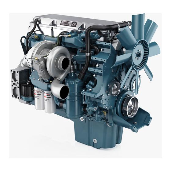
Refer to DDEC Troubleshooting Guide 2. ENGINE-MOUNTED COMPONENTS FIGURE 1: DETROIT DIESEL SERIES 60 ENGINE (TYPICAL) 01015 • Coolant Temperature Sensor Engine-mounted components are as follows: • Electronic Control Module •... -
Page 4: Electronic Control Module
EEPROM within Electronic Control Module is factory programmed by Detroit Diesel. Reprogramming must be done at a Detroit Diesel authorized service center. However, some changes may be performed to the cruise control and road speed limiter using a diagnostic data reader (see paragraph "DDEC IV Diagnostic Codes"... -
Page 5: Timing Reference Sensor
Section 01: ENGINE The TRS connector is gray. The TRS sensor sends a signal to the ECM. The TRS senses a series of evenly spaced special teeth on the timing wheel. A tooth passes by the TRS as each cylinder crank pin reaches 10° before Top- Dead-Center. -
Page 6: Coolant Temperature Sensor
Section 01: ENGINE provides input data to vary hot idle speed and injection timing. This helps to improve cold starts and reduces white exhaust smoke. 3.6 OIL PRESSURE SENSOR The Oil Pressure Sensor (OPS) is installed in the main engine-oil gallery. A typical location is the left rear corner of the cylinder block (Fig. -
Page 7: Coolant Level System (Cls)
Section 01: ENGINE • Cruise Control Switch (CCS) • Diagnostic System Accessories (DSA) 4.1 COOLANT LEVEL SYSTEM (CLS) coolant level system consists conductivity probe mounted in the surge tank and an electronic interface module located inside the rear junction box. Coolant level is determined by the change in impedance of the probe and its brass mount when immersed in... -
Page 8: Diagnostic System Accessories (Dsa)
Section 01: ENGINE 4. DECEL: Will cancel the cruise temporarily before engine shutdown when the Stop engine and let the vehicle coast. Set speed is still in telltale light is illuminated. This switch can be memory for resume. repeatedly depressed in order to move the vehicle out of traffic. - Page 9 Section 01: ENGINE can provide the information necessary for a repeats itself until the operator depresses the quick diagnosis of the problem. If you just need stop engine override switch again. A code "43" to read out codes, however, and do not have a consists of four flashes, followed by a short DDR available, the following procedure will let pause, then three flashes in quick succession.
- Page 10 Section 01: ENGINE DDEC DDEC Code Code DESCRIPTION DESCRIPTION Number Number (Flashed) (Flashed) Oil, coolant, intercooler or intake air Coolant level low temperature high Oil pressure low ECM battery voltage low Fuel, inlet turbo boost Fuel or air inlet pressure low pressure high ECM A/D conversion fault ECM non volatile memory fault...
-
Page 11: Engine Oil Level
Detroit Diesel service outlet for the cause. Fuel or coolant dilution of lube oil can result in serious Change engine oil with the vehicle on a flat and engine damage. -
Page 12: Recommended Engine Oil Type
API Service Classification. Note: The use of supplemental oil additives is discouraged from use in Detroit Diesel Engines. Synthetic oils Synthetic oils may be used in Detroit Diesel engines provided they are API- licensed meet performance chemical requirements of non-synthetic oils outlined previously. - Page 13 Section 01: ENGINE must be removed as a whole unit by means of a 4. Locate the belt tensioner control valve slide-out cradle. The power plant assembly (Fig. 14). Turn handle counterclockwise in includes the engine, transmission (including order to release pressure in belt-tensioner air retarder equipped), compressor,...
- Page 14 Section 01: ENGINE 13. Disconnect and remove the air intake duct 16. Disconnect and remove the small hose mounted between the turbocharger outlet and connected to the heater line valve and to the the air cooler inlet (5, Fig. 16). water pump.
-
Page 15: Power Plant Assy. Installation
Section 01: ENGINE 27. Disconnect positive cable (red terminal) from 37. Remove the six retaining bolts, washers and starting motor solenoid. nuts securing the power plant cradle to the vehicle rear subframe (Fig. 18). 28. Disconnect the power plant wiring-harness Note: main connectors from ECM and remove Check if any spacer(s) have been... -
Page 16: Valve Cover Removal
3. Disconnect ventilation pipe from valve cover. 4. Remove engine cover. 5. Adjust Jake Brake (if applicable), injectors and valves following instructions in the Detroit Diesel service manual for series 60 engines. 6. Verify engine cover gasket and replace if necessary. -
Page 17: Figure 18: Power Plant Cradle Installation
Section 01: ENGINE FIGURE 18: POWER PLANT CRADLE INSTALLATION 01032 01-17... -
Page 18: Specifications
Section 01: ENGINE 15. SPECIFICATIONS Series 60 Engine Make ............................Detroit Diesel Type....................... Diesel four cycle/in-line engine Description.......................Turbo/Air to air charge cooled No. of cylinders ............................. 6 Operating range........................1200-2100 RPM Maximum RPM ............................2100 Displacement, 11.1 Liters: Bore & Stroke ..................... 5.12 X 5.47 in (130 X 139 mm) Horsepower Range .......................285 BHP, 350 BHP... - Page 19 Section 01: ENGINE Make..........................Nelson # 70337-N Prévost number ..........................530197 Engine Coolant Filter/Conditioner Make..................... Nalco Chemical Company # DDF3000 Make......................... Detroit Diesel # 23507545 Prévost number ..........................550630 Note: For primary and secondary fuel filters, refer to Specifications in section 03. 01-19...
Need help?
Do you have a question about the 60 Series and is the answer not in the manual?
Questions and answers