Advertisement
Quick Links
Advertisement

Related Manuals for Simpli Home Acadian


Summary of Contents for Simpli Home Acadian
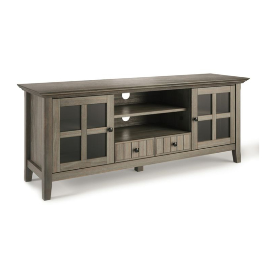
- Page 1 60 INCH TV MEDIA STAND 1/21...
- Page 2 Questions, problems, assembly help, missing parts? No need to return the product, we will gladly help and ship your replacement parts free of charge Please call Customer Service In order to assist you in a timely manner, please have the following information ready: Model # _______________________ Part Number or Letter_______________________ Purchased at ___________________Date of Purchase ___________________________ If you wish to return the product, please contact the retailer where the...
-
Page 3: Safety Information
IMPORTANT : Please read this manual carefully before beginning assembly of this product. Keep this manual for future reference. SAFETY INFORMATION CAUTION: Injuries and damage can occur from furniture tip over if product is not properly anchored to the wall. Use the Furniture Anti-Tipping Restraint provided with the product. -
Page 4: Care And Maintenance
IMPORTANT : Please read this manual carefully before beginning assembly of this product. Keep this manual for future reference. CARE and MAINTENANCE Perhaps the greatest environmental damage to wood furniture comes from wide swings in relative humidity (RH) in our homes. Wood absorbs and desorbs water as relative humidity rises and falls, and in doing so it swells and shrinks. -
Page 5: Pre-Assembly Information
PRE-ASSEMBLY INFORMATION PARTS DESCRIPTION LEFT SIDE RIGHT SIDE QTY 1 QTY 1 QTY 1 SMALL DIVIDER LEFT BIG DIVIDER RIGHT BIG DIVIDER QTY 1 QTY 1 QTY 1 BOTTOM SHELF CENTRE SHELF LARGE SHELF QTY 1 QTY 1 QTY 1 LEFT BACK PANEL SMALL SHELF DOOR (L&R Same) - Page 6 PRE-ASSEMBLY INFORMATION PARTS DESCRIPTION RIGHT BACK PANEL TOP BACK PANEL BOTTOM BACK PANEL QTY 1 QTY 1 QTY 1 BOTTOM SUPPORT LEG LEFT DRAWER FRONT RIGHT DRAWER FRONT QTY 1 QTY 1 QTY 1 DRAWER BACK LEFT DRAWER SIDE RIGHT DRAWER SIDE QTY 2 QTY 2 QTY 2...
- Page 7 PRE-ASSEMBLY INFORMATION HARDWARE DESCRIPTION CAM LOCK PIN WOOD DOWEL ALLEN KEY SCREW M6 X 30 mm CAM LOCK 8 X 30 mm ALLEN KEY QTY 23 QTY 14 QTY 1 QTY 29 PHILLIPS SHORT PHILLIPS SCREW PHILLIPS MEDIUM ROUND HEAD SCREW SCREW SHELF SUPPORT...
- Page 8 COMPONENTS – KEY DIAGRAM 8/21...
- Page 9 ASSEMBLY STEP 1 1. Attach 4 Cam Lock Pins 2 to back of Left Drawer Front LL . 2. Align Cam Lock Pins with pre-drilled holes and attach Drawer Sides ML , MR . 3. Insert 2 Cam Locks 2 into pre-drilled holes on each Drawer Side ML , MR . 4.
- Page 10 ASSEMBLY STEP 3 1. Align Drawer Back N with Drawer Bottom O and press firmly into slot . 2. Attach back using 2 Allen Key Screws 1 through pre-drilled holes on each Side M . 3. Use Allen Key 4 to tighten screws. Do not over-tighten. STEP 4 NOTE: The screwdriver is not included in the hardware pack.
- Page 11 ASSEMBLY STEP 5 1. Attach 3 Cam Lock Pins 2 to each Big Divider CL , CR into guide holes. 2. Align and insert Cam Lock Pins on Big Dividers CL , CR into pre-drilled holes on Centre Shelf F . 3.
- Page 12 ASSEMBLY STEP 7 1. Insert 2 Dowels 3 into pre-drilled holes on each Big Divider CL , CR and Small Divider D . 2. Use rubber mallet to tap Dowels 3 into bottom of holes securely. ½ length of Dowels should be exposed. 3.
- Page 13 ASSEMBLY STEP 8 1. Insert 2 Dowels 3 into pre-drilled holes on each Side BL , BR . 2. Use rubber mallet to tap Dowels 3 into bottom of holes securely. ½ length of Dowels should be exposed. 3. Attach 3 Cam Lock Pins 2 to each Side BL , BR into guide holes. 4.
- Page 14 ASSEMBLY STEP 9 1. Insert 2 Dowels 3 into top corners of each Side BL , BR . 2. Use rubber mallet to tap Dowels 3 into bottom of holes securely. ½ length of Dowels should be exposed. 3. Align pre-drilled holes bottom corners of Top A with Dowels 3 on Sides BL , BR . 4.
- Page 15 ASSEMBLY STEP 10 1. Attach Bottom Support Leg K to Bottom Shelf E using 4 Phillips Screws 9 . 2. Use Phillips screwdriver to tighten screws. Do not over-tighten. 15/21...
- Page 16 ASSEMBLY STEP 11 1. Attach Back Panels JL , JR , J1 , J2 to Back of cabinet using Phillips Screws Round Head 5 into pre-drilled guide holes. 2. Use Phillips screwdriver to tighten screws. Do not over-tighten. 16/21...
- Page 17 ASSEMBLY STEP 12 1. Attach hinges on Doors I to Sides BL , BR using Phillips Screws 7 into pre-drilled guide holes. 2. Attach Magnet Plates 11 to bottom corner of Doors I using Phillips Screws 8 . into guide holes on Doors I . 3.
- Page 18 ASSEMBLY STEP 13 & 1. Use 4 Shelf Supports 6 for each Shelf G & H in desired location. 2. 2 Shelf Supports 6 may be used on back top of each Shelf G & H as a tipping restraint. 18/21...
- Page 19 FURNITURE TIP OVER RESTRAINT ASSEMBLY WARNING Serious or fatal crushing injuries can occur from furniture tip-over. If the furniture tip over restraint kit is not in the box, please contact our customer service department in order to obtain another kit before using the furniture. STEP 14 NOTE: The screwdriver is not included in the hardware pack.
- Page 20 FURNITURE TIP OVER RESTRAINT ASSEMBLY Furniture Tip Over Restraint Instructions: Attach one of the mounting brackets securely to the back edge of the furniture. Use the shorter screw. Determine where furniture is to be placed and mark location on the wall for mounting bracket screw hole approximately 2 inches below the bracket mounted to the furniture.
-
Page 21: Warranty
WARRANTY Thank you for purchasing a product. These products have been made to demanding, high-quality standards and are guaranteed for domestic use against manufacturing faults for a period of 12 months from the date of purchase. This warranty does not affect your statutory rights. In case of any malfunction of your product (failure, missing parts, etc.) please contact us at our toll free service line We reserve the right to repair or replace the defective product, at its...
Need help?
Do you have a question about the Acadian and is the answer not in the manual?
Questions and answers