Table of Contents
Advertisement
Available languages
Available languages
Quick Links
AUTOMOTIVE PRODUCTS, INC.
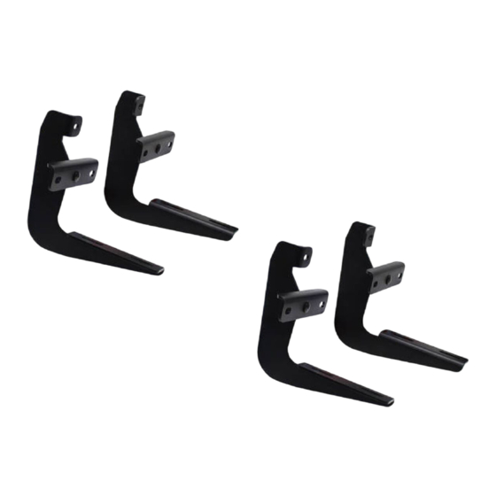
MOUNT KIT
EQUIPO DE MONTAJE
OPTIONAL LIGHT
JEU DE MONTAGE
27-1675
MOLDED
SURE-GRIP
STEP
BOARDS
27-6130
BOARDS
27-0010
27-6135
27-0015
27-6530
CONTENTS - CONTENIDO - CONTENU
ITEM
QTY
1
2
STEP BOARD (PURCHASED SEPARATELY)
2
2
FRONT BRACKET
3
2
CENTER BRACKET
4
2
REAR BRACKET
5
12
5/16-18 X 1.00" HEX HEAD BOLT
6
30
5/16" USS FL AT WASHER
7
12
5/16" LOCK WASHER
8
6
5/16-18 HEX NUT
9
12
5/16-18 X .75" SQUARE HEAD BOLT
10
12
5/16-18 LOCK NUT
11
6
EXTRUDED U-NUT
1
2
ESTRIBOS (SE COMPRAN POR SEPARADO)
2
2
SOPORTES DELANTERAS
3
2
SOPORTES CENTRALES
4
2
SOPORTES TRASERAS
5
12
PERNOS CON CABEZA HEXAGONAL DE 5/16-18 X 1,00"
6
30
ARANDELAS PLANAS DE USS 5/16"
7
12
ARANDELAS DE PRESIÓN DE 5/16"
8
6
TUERCAS HEXAGONALES DE 5/16-18
9
12
PERNOS CON CABEZA CUADRADA DE 5/16"
10
12
TUERCA PRESIÓN DE 5/16-18
11
6
TUERCA A PRESIÓN EN "U"
1
2
MARCHEPIED (VENDU SÉPARÉMENT)
2
4
SUPPORTS AVANT
3
2
SUPPORTS CENTRAL
4
2
SUPPORTS ARRIERE
5
12
BOULONS A TETE HEXAGONALE 5/16-18 X 1,00 PO
6
30
RONDELLES PLATES USS 5/16 PO
7
12
RONDELLES A FREIN 5/16 PO
8
6
ÉCROUS HEXAGONAUX 5/16-18
9
12
BOULON A TETE CARREE 5/16 PO
10
12
ECROU A FREIN 5/16-18
11
6
ECROU EN U EXTRUDE
Remove contents from box and check for damage. Verify all parts are present. Read and understand instructions before beginning.
STEP 1.
NOTE: If installing Westin step boards on vehicles equipped with factory step boards, the existing factory hardware can be used. The
mount brackets will be placed over the mounting stud protruding from the rocker panel, and the factory nuts can be reused. It is
strongly recommended to install the Sure Grip Gap Strip for these vehicle applications.
STEP 2.
Locate the pair of holes on the bottom of the rocker panel and the square hole next to the round hole on the bottom of the floor
pan. SEE FIGURE 1.
STEP 3.
Insert extruded "u" nut through square hole in vehicle floor plan so it is positioned over the round hole. SEE FIGURE 1.
Install front, center, and rear brackets to the extruded "u" nuts inserted into the vehicle floor pan with 5/16" fasteners as shown. SEE
STEP 4.
FIGURE 1.
Install front, center, and rear brackets to vehicle rocker panel with 5/16" fasteners as shown. SEE FIGURE 1 for hole locations.
STEP 5.
STEP 6.
Insert square head bolts as shown (3 per slot, 6 per Step board/Running board). See Figures 3 and 4. NOTE: For lighted boards, run
wiring harness prior to attaching board to brackets (refer to Step 4). SEE FIGURES 3 AND 4. Run longer wire harness on passenger
side.
STEP 7.
For Sure-Grip Running Boards, slide closure strip as shown. Set lights (if purchased) in appropriate location. Attach to Sure-Grip Running
Board as shown. SEE FIGURE 2. Drill hole through plastic strip and run wires as shown. SEE FIGURE 5.
STEP 8.
Attach Step board / Running board to brackets as shown. Make sure step board and brackets are properly aligned and tighten
fasteners. Recommended torque values are 10 FT.LBS. for 5/16" square head fasteners and 16 FT.LBS. for 5/16" fasteners. SEE
FIGURE 6. NOTE: For lighted version of Step board, remove plastic cover from each end of under side of Step board. Proceed to
Steps 9 and 10.
WARNING: INSTALLING LIGHT HARNESS REQUIRES SPLICING INTO VEHICLES ELECTRICAL SYSTEM. WESTIN RECOMMENDS USING A PROFESSIONAL
FOR THIS INSTALLATION. NOTE: AVOID AREAS OF EXCESSIVE HEAT, VIBRATION, PINCH OR ROTATION WHEN SECURING HARNESS TO
INSTRUCTIONS-INSTRUCCIONES-CONSIGNES
APPLICATION: 2006-08 FORD EXPLORER; MERCURY MOUNTAINEER
APLICACIÓN: FORD EXPLORER/ MERCURY MOUNTAINEER, MOD.2006-08
APPLICATION:
SURE-GRIP
KIT
27-6000
1
2006-08 FORD EXPLORER/ MERCURY MOUNTAINEER
2
3
TOOLS-HERRAMIENTA -OUTILS
1/2" SOCKET
1/2" WRENCH
RATCHET
RATCHET EXTENSION
TORQUE WRENCH
DADO DE 1/2"
LLAVE DE TUERCAS DE 1/2"
MANERAL
MANERAL EXTENSION
LLAVE DE TORQUE
DOUILLE 1/2 PO
CLEF 1/2 PO
CLIQUET
CLIQUET RALLONGE
CLÉ DE COUPLE
WO:
75-0757 REVISION D 6/30/08
11
4
Advertisement
Table of Contents

Related Manuals for Westin 27-1675


Summary of Contents for Westin 27-1675
- Page 1 STEP 1. NOTE: If installing Westin step boards on vehicles equipped with factory step boards, the existing factory hardware can be used. The mount brackets will be placed over the mounting stud protruding from the rocker panel, and the factory nuts can be reused. It is strongly recommended to install the Sure Grip Gap Strip for these vehicle applications.
- Page 2 FINISH PROTECTION Westin products have a high quality finish that must be cared for like any other exposed finish on the vehicle. Protect the finish with a non-abrasive automotive wax, (e.g. Pure Carnauba) on a regular basis. The use of any soap, polish or wax that contains an abrasive is detrimental, as the compounds scratch the finish and open it to corrosion.
- Page 3 PROTECTION DE LA FINISSION Les produits Westin ont une finission de haute qualité qui requiert des soins, comme toute autre finission du véhicule exposée aux éléments. Protégez la finission à l’aide d’une cire non-abrasive (par exemple, Pure Carnauba) de façon régulière. L’usage de tout savon, pâte à polir ou cire contenant un abrasif est nuisible, puisque les composantes strient la finission et la laissent vulnérable à...
- Page 4 FLOOR PAN PISO DEL VEHÍCULO PLANCHER DU VÉHICULE ROCKER PANEL PANEL BAJO LA PUERTA BAS DE CAISSE FIGURE 1 INSTALLATION VIEW OF PASSENGER SIDE SHOWN, DRIVER SIDE OPPOSITE FIGURA 1 VISTA DE LA INSTALACIÓN DEL LADO DEL ACOMPAÑANTE OPUESTO AL LADO DEL CONDUCTOR FIGURE 1 ILLUSTRE: COTE PASSAGER , EN FACE: COTE CONDUCTEUR FIGURE 2 FIGURA 2...
Need help?
Do you have a question about the 27-1675 and is the answer not in the manual?
Questions and answers