
Related Manuals for Seeed ODYSSEY STM32MP157C


Summary of Contents for Seeed ODYSSEY STM32MP157C
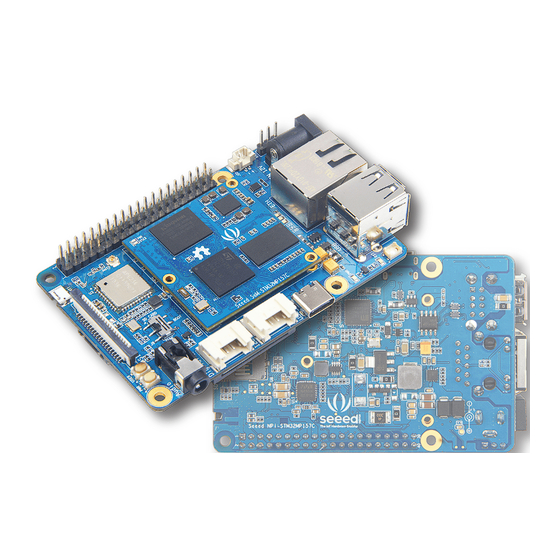
- Page 1 ODYSSEY – STM32MP157C System-On-Module + Carrier Single Board Computer Reference Guide Revision A March 27, 2020 www.seeed.cc...
-
Page 2: Table Of Contents
Carrier Board Hardware Overview Carrier Board pinout diagram ................SoM component details ..................Carrier Board component details ..............6 FCC Regulatory Compliance Information End Device Labelling ..................RF Exposure Compliance .................. Installation Notice ..................... 8 www.seeed.cc Page 2 Rev A... -
Page 3: Overview Description
• Raspberry Pi 40-Pin Compatible Carrier Board • Compact Size and Powerful • Open-Source Hardware/SDK/API/BSP/OS Applications • Industrial (CAN-Ethernet gateways) • White goods (refrigerators, microwaves) • Medical (data loggers) • High-end wearables (VR devices) • Smart Home Devices www.seeed.cc Page 3 Rev A... -
Page 4: Specifications
1 x DC Jack 12V~24V/2A (12V/2A power input is recommended) 1 x USB Type-C • Button 1 x Reset 1 x User 1 x Switch • Dimensions: 56mm x 85mm • Operating Temperature: 0 ~ 75°C www.seeed.cc Page 4 Rev A... -
Page 5: Hardware Overview
ODYSSEY – STM32MP157C Reference Guide Hardware Overview Carrier Board Pinout Diagram ODYSSEY - STM32MP157C’s 40-pins are fully compatible with Raspberry Pi's 40-pins including GPIO, I2C, UART, SPI, I2S and PWM pins. SoM Components Details www.seeed.cc Page 5 Rev A... -
Page 6: Carrier Board Component Details
4.EMMC04G-M627: 4GB eMMC Memory 5.LED: When the power supply is successful, the PWR LED will turn on. When the system is running normally, the USER LED will keep flashing. 6, 7, 8: 70-PIN connectors Carrier Board Components Details www.seeed.cc Page 6 Rev A... - Page 7 ODYSSEY – STM32MP157C Reference Guide 1.Seeed SoM-STM32MP157C Installation Area: If the user wants to remove the core board, slowly tilt the core board up and then remove. Never remove by hand. 2.DC Power Input Port: 12V~24V/2A (12V/2A power input is recommended).
-
Page 8: Fcc Regulatory Compliance Information
Increase the separation between the equipment and receiver. • Connect the equipment into an outlet on a circuit different from that to which the receiver is connected. • Consult the dealer or an experienced radio/TV technician for help. www.seeed.cc Page 8 Rev A... - Page 9 If you want to learn about setting up the software and other details, please visit the product wiki at http://wiki.seeedstudio.com/ODYSSEY-STM32MP157C/ If you still have any further questions, please visit forum.seeedstudio.com © 2008-2020 Seeed Technology Co.,Ltd. All rights reserved. www.seeed.cc Page 9 Rev A...
Need help?
Do you have a question about the ODYSSEY STM32MP157C and is the answer not in the manual?
Questions and answers