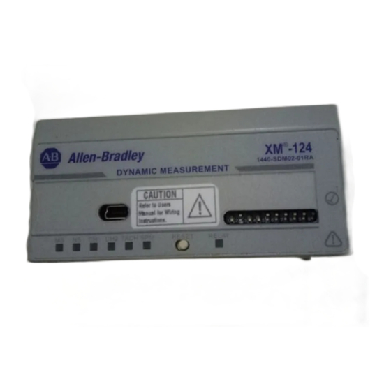
Summary of Contents for Rockwell Automation Allen-Bradley XM-124
-
Page 1: Table Of Contents
Installation Instructions XM-124 Standard Dynamic Measurement Module Catalog Number 1440-SDM02-01RA Topic Page Important User Information North American Hazardous Location Approval Wiring Requirements Install the Module Additional Resources... -
Page 2: Important User Information
In no event will Rockwell Automation, Inc. be responsible or liable for indirect or consequential damages resulting from the use or application of this equipment. -
Page 3: North American Hazardous Location Approval
Classe I, Division 2. • If this product contains batteries, • S'assurer que l'environnement est they must only be changed in an classé non dangereux avant de area known to be nonhazardous. changer les piles. Rockwell Automation Publication 1440-IN001B-EN-P - October 2013... -
Page 4: Wiring Requirements
7. Establish a DeviceNet connection. ATTENTION: The XM-124 Dynamic Measurement Module is certified and approved for use only in the 1440-TB-A/C terminal base unit. Do not install the XM-124 module in any other terminal base unit. Rockwell Automation Publication 1440-IN001B-EN-P - October 2013... - Page 5 Interruption of the backplane can result in unintentional operation or machine motion. DIN Rail Mounting Use the following steps to mount the terminal base unit on a DIN rail (Allen-Bradley catalog number 199-DR1 or 199-DR4). Rockwell Automation Publication 1440-IN001B-EN-P - October 2013...
- Page 6 2. Slide the terminal base unit over, leaving room for the side connector (B). 3. Rotate the terminal base unit onto the DIN rail with the top of the rail hooked under the lip on the rear of the terminal base unit. 31883-M Rockwell Automation Publication 1440-IN001B-EN-P - October 2013...
- Page 7 Wiring to the module is made through the terminal base unit on which the module mounts. The XM-124 module is compatible only with the XM-940 terminal base unit, catalog number 1440-TB-A. XM-940 Terminal Base Unit XM-940 (catalog number 1440-TB-A) Rockwell Automation Publication 1440-IN001B-EN-P - October 2013...
- Page 8 Secure any external connections that mate to this equipment by using screws, sliding latches, threaded connectors, or other means provided with this product. Rockwell Automation Publication 1440-IN001B-EN-P - October 2013...
- Page 9 Xducer 1 (-) Vibration transducer 1 connection Xducer 2 (-) Vibration transducer 2 connection Signal Common Vibration buffered output return TACH Buffer Tachometer transducer/signal output Tachometer (-) Tachometer transducer/signal return, TACH Buffer return Rockwell Automation Publication 1440-IN001B-EN-P - October 2013...
- Page 10 Connection to DIN-rail ground spring or panel mounting hole Chassis Chassis Chassis Chassis Chassis Chassis Chassis SetPtMult Switch input to activate Set Point Multiplication (active closed) Switch RTN Switch return, shared between SetPtMult and Reset Relay Rockwell Automation Publication 1440-IN001B-EN-P - October 2013...
- Page 11 This can cause an explosion in hazardous location installations. Be sure that power is removed or the area is nonhazardous before proceeding. Install the overlay slide label to protect the serial connector and electronics IMPORTANT when the serial port is not in use. Rockwell Automation Publication 1440-IN001B-EN-P - October 2013...
- Page 12 5. Press firmly and evenly to seat the module in the terminal base unit. The module is seated when the latching mechanism (C) is locked into the module. 6. Repeat the above steps to install the next module in its terminal base unit. Rockwell Automation Publication 1440-IN001B-EN-P - October 2013...
- Page 13 XM modules linked to the wired terminal base unit via the side connector. ATTENTION: The power connections vary for different XM modules. Refer to the installation instructions for your specific XM module for complete wiring information. Rockwell Automation Publication 1440-IN001B-EN-P - October 2013...
- Page 14 Pin 5 (SG - signal ground) • Mini-connector - The mini-connector is on the top of the module, as shown below. Mini-connector Mini-connector A special cable (catalog number1440-SCDB9FXM2) is required for this connection. Rockwell Automation Publication 1440-IN001B-EN-P - October 2013...
- Page 15 XM-124 module. As multiple XM modules are interconnected, the DeviceNet network also serves as the communication bus and protocol that efficiently transfers data between the XM modules. Rockwell Automation Publication 1440-IN001B-EN-P - October 2013...
- Page 16 10. ATTENTION: The DeviceNet network must also be referenced to earth ground at only one location. Connect DNet V- to earth ground or chassis at one of the XM modules. Rockwell Automation Publication 1440-IN001B-EN-P - October 2013...
- Page 17 DeviceNet behavior, node address, and communication rate. The switches are numbered from left to right and are applied as shown in the illustration below and in the following table. DIP Switch Bank Rockwell Automation Publication 1440-IN001B-EN-P - October 2013...
- Page 18 When switch 1 is off (0), the DeviceNet 125 Kbps Both off communication rate is set. 5…10 Node When switch #1 is off (0), the DeviceNet All on address node address is set. Rockwell Automation Publication 1440-IN001B-EN-P - October 2013...
-
Page 19: Additional Resources
Provides declarations of conformity, certificates, and other certification details. You can view or download publications at http://www.rockwellautomation.com/literature/. To order paper copies of technical documentation, contact your local Allen-Bradley distributor or Rockwell Automation sales representative. Rockwell Automation Publication 1440-IN001B-EN-P - October 2013... - Page 20 New Product Satisfaction Return Rockwell Automation tests all of its products to help ensure that they are fully operational when shipped from the manufacturing facility. However, if your product is not functioning and needs to be returned, follow these procedures.


Need help?
Do you have a question about the Allen-Bradley XM-124 and is the answer not in the manual?
Questions and answers