HIKVISION DS-9000 Series Quick Start Manual
All-in-one server
Hide thumbs
Also See for DS-9000 Series:
- User manual (137 pages) ,
- Quick start manual (13 pages) ,
- Technical manual (9 pages)
Table of Contents
Advertisement
Advertisement
Table of Contents

Related Manuals for HIKVISION DS-9000 Series


Summary of Contents for HIKVISION DS-9000 Series
- Page 1 All-in-One Server Quick Start Guide...
-
Page 2: Table Of Contents
All-in-One Server Quick Start Guide TABLE OF CONTENTS Chapter 1 Panels Description ................................. 6 1.1 Front Panel ....................................6 1.2 Rear Panel ....................................7 Chapter 2 Installation and Connections ............................9 2.1 Installation ....................................9 2.2 HDD Installation ..................................9 2.2.1 Installing HDD in Storage Board ............................9 2.2.2 Installing HDD in Server Board ............................12 2.3 Connections .....................................14 2.3.1 Alarm Input Wiring ...............................14... - Page 3 INDIRECT DAMAGES, INCLUDING, AMONG OTHERS, DAMAGES FOR LOSS OF BUSINESS PROFITS, BUSINESS INTERRUPTION, OR LOSS OF DATA OR DOCUMENTATION, IN CONNECTION WITH THE USE OF THIS PRODUCT, EVEN IF HIKVISION HAS BEEN ADVISED OF THE POSSIBILITY OF SUCH DAMAGES. REGARDING TO THE PRODUCT WITH INTERNET ACCESS, THE USE OF PRODUCT SHALL BE WHOLLY AT YOUR OWN RISKS.
- Page 4 All-in-One Server Quick Start Guide Regulatory Information FCC Information Please take attention that changes or modification not expressly approved by the party responsible for compliance could void the user’s authority to operate the equipment. FCC compliance: This equipment has been tested and found to comply with the limits for a Class A digital device, pursuant to part 15 of the FCC Rules.
- Page 5 All-in-One Server Quick Start Guide Applicable Models This manual is applicable to the models listed in the following table. Product Model DS-9000 series all-in-one server DS-9000AI-S16-D Blazer Pro/128/16H Blazer series iVMS station Blazer Pro/256/16H Symbol Conventions The symbols that may be found in this document are defined as follows.
- Page 6 All-in-One Server Quick Start Guide Safety Instructions Proper configuration of all passwords and other security settings is the responsibility of the installer and/or end-user. In the use of the product, you must be in strict compliance with the electrical safety regulations of the nation and region.
-
Page 7: Chapter 1 Panels Description
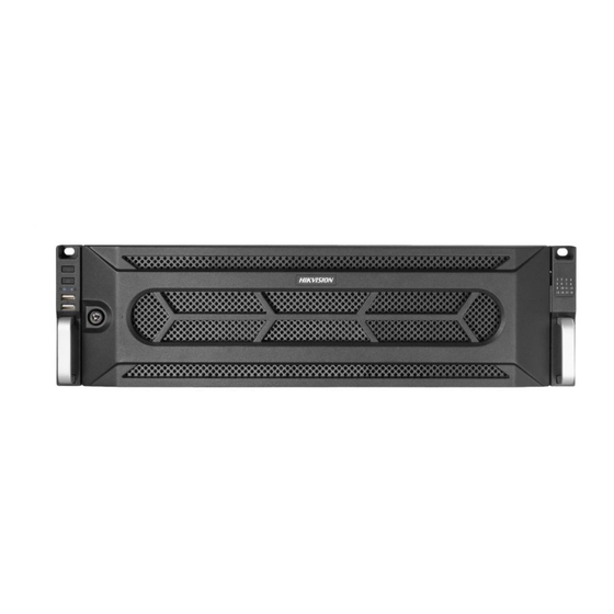
All-in-One Server Quick Start Guide Chapter 1 Panels Description 1.1 Front Panel DS-9000AI-S16-D Series Figure 1-1 DS-9000AI-S16-D Series Blazer Pro/128/16H and Blazer Pro/256/16H Series Figure 1-2 Blazer Pro/128/16H and Blazer Pro/256/16H Series... -
Page 8: Rear Panel
All-in-One Server Quick Start Guide Table 1-1 Description No. Name Description Panel lock Locks or unlocks the panel by the key. Powers on/off device. Power switch Solid blue: device is running. Solid red: device is shut down. Turn on/off buzzer. Muting switch Solid blue: buzzer is turned off. - Page 9 All-in-One Server Quick Start Guide Figure 1-3 Rear Panel Table 1-2 Panel Description Name Name Server board RS-232 interface Storage board Power supply module HDMI video output Mini SAS interface Audio input/output Reset button USB 3.0 interface RS-485 interface Network interface Keyboard interface eSATA interface Alarm input/output...
-
Page 10: Chapter 2 Installation And Connections
All-in-One Server Quick Start Guide Chapter 2 Installation and Connections 2.1 Installation During installation of the NVR: Use brackets for rack mounting. Ensure ample room for audio and video cables. When routing cables, ensure that the bend radius of the cables are no less than five times than its diameter. - Page 11 All-in-One Server Quick Start Guide Figure 2-1 Unlock the Bezel Step 2 To remove the bezel from front panel, follow steps below: 1) Slightly pull the bezel out of the device along the direction arrow ① and make it a little above the left mounting ear.
- Page 12 All-in-One Server Quick Start Guide Step 4 Fix the HDD in the HDD tray. 1) Place an HDD in the HDD tray. The SATA interface must face the HDD tray bottom. 2) Adjust the HDD position. Ensure the HDD screw holes aligning with tray screw holes. 3) Use a screwdriver to fasten the four screws into the screw holes in both sides.
-
Page 13: Installing Hdd In Server Board
All-in-One Server Quick Start Guide Figure 2-7 Reinstall the Bezel and Lock 2.2.2 Installing HDD in Server Board Step 1 Unfasten the screws on the back and side of cover. Figure 2-8 Unfasten Screws Step 2 Push the cover along the direction shown in Figure 2-9 to remove it. Figure 2-9 Push Cover Step 3 Unfasten screws on HDD tray and take out the HDD tray Figure 2-10 Unfasten Screw... - Page 14 All-in-One Server Quick Start Guide Step 4 Place a 2.5-inch HDD in HDD tray and fix them with four screws. Figure 2-11 Connect HDD and HDD Tray Step 5 Place the HDD tray back and connect it with the server board. Figure 2-12 Place HDD Step 6 Fix the HDD tray to server board with four screws.
-
Page 15: Connections
All-in-One Server Quick Start Guide 2.3 Connections 2.3.1 Alarm Input Wiring The alarm input is an open/closed relay. To connect the alarm input to the device, use the following diagram. If the alarm input is not an open/close relay, please connect an external relay between the alarm input and the device. -
Page 16: Use Alarm Connectors
All-in-One Server Quick Start Guide If you connect an AC load to the alarm output 3 of the NVR, then you must remove the JP 3 jumper. 2.3.3 Use Alarm Connectors To connect alarm devices to the NVR: Step 1 Disconnect pluggable block from the ALARM IN /ALARM OUT terminal block. Step 2 Unfasten stop screws from the pluggable block, insert signal cables into slots and fasten stop screws. -
Page 17: Hdd Storage Calculation Chart
All-in-One Server Quick Start Guide 2.4 HDD Storage Calculation Chart The following chart shows an estimation of storage space used based on recording at one channel for an hour at a fixed bit rate. Bit Rate Storage Used 128K 160K 192K 224K 256K... -
Page 18: Chapter 3 Menu Operation
All-in-One Server Quick Start Guide Chapter 3 Menu Operation 3.1 Start up Your Device Proper startup and shutdown procedures are crucial to expanding the life of the NVR. To start your device: Step 1 Check the power supply is plugged into an electrical outlet. It is HIGHLY recommended that an Uninterruptible Power Supply (UPS) be used in conjunction with the device. -
Page 19: Configure Unlock Pattern For Login
All-in-One Server Quick Start Guide Figure 3-1 Setting Admin Password We highly recommend you create a strong password of your own choosing (Using a minimum of 8 characters, including at least three of the following categories: upper case letters, lower case letters, numbers, and special characters.) in order to increase the security of your product. -
Page 20: Log Into The System
All-in-One Server Quick Start Guide Step 1 After the device is activated, you can enter the following interface to configure the device unlock pattern. Step 2 Use the mouse to draw a pattern among the 9 dots on the screen. Release the mouse when the pattern is done. -
Page 21: Enter Wizard To Configure Quick Basic Settings
All-in-One Server Quick Start Guide Figure 3-3 Login Interface Step 3 Input Password. Step 4 Click Login. In the Login dialog box, if you enter the wrong password 7 times, the current user account will be locked for 60 seconds. 3.5 Enter Wizard to Configure Quick Basic Settings The Setup Wizard can walk you through some important settings of the device. -
Page 22: Network Settings
All-in-One Server Quick Start Guide 3.6 Network Settings Purpose: Network settings must be properly configured before you operate device over network. Step 1 Go to System > Network > TCP/IP. Figure 3-5 Network Settings Step 2 Select the General tab. Step 3 In the General Settings interface, you can configure the following settings: NIC Type, IPv4 Address, IPv4 Gateway, MTU and DNS Server. -
Page 23: Start Live View
All-in-One Server Quick Start Guide Step 1 Click on the main menu bar to enter the Camera Management. Step 2 Click the Custom Add tab on the title bar to enter the Add IP Camera interface. Figure 3-6 Add IP Camera Step 3 Enter IP address, protocol, management port, and other information of the IP camera to add. -
Page 24: Recording Settings
All-in-One Server Quick Start Guide The device supports the RAID storage function. Through one-touch configuration, you can quickly create the disk array. By default, the array type to be created is RAID 5. Before you start: Enable RAID function. ... -
Page 25: Playback
All-in-One Server Quick Start Guide Step 3 Check Enable Schedule. Step 4 Select a record type. The record type can be Continuous, Motion Detection, Alarm, Motion | Alarm, Motion & Alarm, Event, etc. Figure 3-8 Record Schedule Step 5 Select a day and click-and-drag the mouse on the time bar to set the record schedule. Step 6 Click Apply to save the settings. - Page 26 All-in-One Server Quick Start Guide Figure 3-9 Playback Interface...
-
Page 27: Chapter 4 Access By Web Browser
All-in-One Server Quick Start Guide Chapter 4 Access by Web Browser You shall acknowledge that the use of the product with Internet access might be under network security risks. For avoidance of any network attacks and information leakage, please strengthen your own protection. - Page 28 All-in-One Server Quick Start Guide If the device is already activated, enter the user name and password in the login interface, and click the Login button. Figure 4-2 Login Step 3 Install the plug-in before viewing the live video and managing the camera. Please follow the installation prompts to install the plug-in.
-
Page 29: Chapter 5 Installing Operation System
All-in-One Server Quick Start Guide Chapter 5 Installing Operation System Operation system can be installed in the server board. Ubuntu Linux operation system is installed when delivered. You can install following Microsoft Windows as well: Windows 7E, Windows 10, and Windows Server 2012 R2. For detailed steps about operation system installation, refer to the Installation Guide. - Page 30 UD07823B...
Need help?
Do you have a question about the DS-9000 Series and is the answer not in the manual?
Questions and answers