HIKVISION DS-9000 User Manual
Hide thumbs
Also See for DS-9000:
- User manual (137 pages) ,
- Quick start manual (30 pages) ,
- Technical manual (9 pages)
Table of Contents
Advertisement
Quick Links
Advertisement
Table of Contents

Related Manuals for HIKVISION DS-9000


Summary of Contents for HIKVISION DS-9000
- Page 1 DS-9000/DS-9100 Series DVR USER’S MANUAL Version 1.1.0...
- Page 2 The content of this manual is furnished for informational use only, is subject to change without notice, and should not be construed as a commitment by Hikvision Digital Technology Co., Ltd. (Hikvision). Hikvision assumes no responsibility or liability for any errors or inaccuracies that may appear in the book.
-
Page 3: Preventive And Cautionary Tips
Preventive and Cautionary Tips Before connecting and operating your DVR, please be advised of the following tips: • Ensure unit is installed in a well-ventilated, dust-free environment. • Unit is designed for indoor use only. • Keep all liquids away from the DVR. •... -
Page 4: Table Of Contents
TABLE OF CONTENTS C H A P T E R 1 ............................. 6 Introduction ............................6 Overview ............................7 Product Key Features ........................7 Product Application Diagram ....................... 10 Operating Your DVR ........................10 Rear Panel Diagram ........................15 C H A P T E R 2 ........................... 17 Getting Started ............................ - Page 5 Alarm Settings ............................. 51 Configuring Alarms ........................52 Setting up Motion Detection ....................52 Setting up Sensor Alarms ...................... 54 Triggering Alarm Outputs Manually..................56 Detecting Video Loss ......................57 Detecting Video Tampering ....................58 Setting Exception .......................... 60 Understanding Exception Trigger Options ................61 C H A P T E R 8 ...........................
- Page 6 Deleting a User ........................98 Modifying a User ........................98 Managing System .......................... 99 Importing & Exporting Configuration .................. 99 Updating System Firmware ......................99 Restoring Default Settings ......................101 Viewing System Information ...................... 101 Viewing System Logs ......................... 102 C H A P T E R 1 3 ..........................
-
Page 7: Chapter 1
C H A P T E R 1 Introduction... -
Page 8: Overview
HIKVISION. Built on an embedded platform and combining the latest in advanced H.264 video encoding and decoding technologies, the DS-9000/DS-9100 contains the perfect combination of rock-solid reliability and high performance. The DS-9000 supports both analog and network cameras and can be used as a standalone DVR, hybrid DVR or as an NVR. - Page 9 Alarm & Exception: • Unified management of DVR and IP camera alarm in/out of DS-9000. • Unified management of DVR alarm in/out of DS-9100. • Unified management of DVR and IP camera motion detection, view tampering and video lost of DS-9000.
- Page 10 • Unified management of DVR motion detection, view tampering and video lost of DS-9100. • Supports alarm in/out arming schedule setting. • Supports various alarm input such as hard disk full, illegal access, network break, IP conflicted, hard disk error, video exception, and video output standard mismatch.
-
Page 11: Product Application Diagram
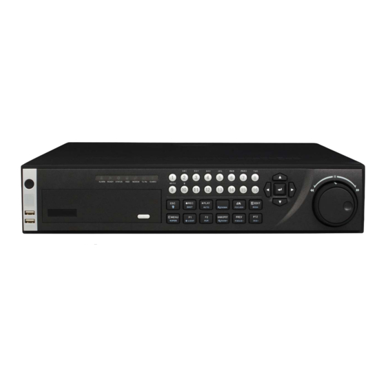
Product Application Diagram Figure 3. Product Application Diagram Operating Your DVR There are numerous ways to navigate and operate your DVR. You may use the Front Panel Controls, the included IR (Infra-Red) Remote, a Mouse and the Soft Keyboard. Using the Front Panel Controls Your DVR comes with built-in front panel controls, as shown in Figure 4. - Page 12 Figure 4. DVR Front Panel Controls The controls on the front panel include: Power Button: Powers DVR on/off. IR Receiver: Receiver for IR remote. USB Ports: Universal Serial Bus (USB) ports for additional devices such as USB mouse and USB Hard Disk Drive (HDD).
-
Page 13: Using The Ir Remote Control
mode, the MENU/WIPER button will start wiper (if applicable). • F1/LIGHT Button: The F1/LIGHT button when used in a list field will select all items on the list. In PTZ Control mode, it will turn on/off PTZ light. • F2/AUX Button: The F2/AUX button is used to cycle through tab pages. It will also bring up the Channel &... - Page 14 Figure 5. IR Remote Control The keys on the remote control closely resemble the ones found on the front panel. Referring to Figure 5, they include: POWER Button: Same as POWER button on front panel. DEV Button: Enables/Disables Remote Control. Alphanumeric Buttons: Same as Alphanumeric buttons on front panel.
-
Page 15: Using A Usb Mouse
18. F2 Button: Same as F2/AUX button on front panel. Aim the remote control at the IR receiver located at the front of the unit to test operation. If there is no response: Using the front control panel or the mouse, go into Menu > Settings > General > More Settings. Check and remember DVR ID#. -
Page 16: Rear Panel Diagram
The buttons on the soft keyboard represents: Lowercase: Designates lowercase input is being used. Uppercase: Designates uppercase input is being used. Switch to Lowercase: Switch to lowercase input. Switch to Uppercase: Switch to uppercase input. Number: Designates number input is being used. Symbols: Switch to symbols input. - Page 17 Loop Out (Optional) DB15 interface for connection video matrix and monitor. RS-232 Interface Connector for RS-232 devices. eSATA (Optional) Connects external SATA HDD, CD/DVD-RM or disk array. LAN Interface Connector for LAN (Local Area Network). USB Interface Connector for USB devices. Termination Switch RS-485 termination switch.
-
Page 18: Getting Started
C H A P T E R 2 Getting Started... -
Page 19: Starting And Shutting Down Your Dvr
Starting and Shutting Down Your DVR Proper startup and shutdown procedures are crucial to expanding the life of your DVR. To startup your DVR: Ensure the power supply is plugged into an electrical outlet. It is HIGHLY recommended that an Uninterruptible Power Supply (UPS) be used in conjunction with the unit. -
Page 20: Using The Setup Wizard
Using the Setup Wizard By default, the Setup Wizard will start once the DVR has loaded, as shown in Figure 2. The Setup Wizard will walk you through some of the more important settings of your DVR. If you do not wish to use the Setup Wizard at this time, click the Cancel button. - Page 21 Figure 4. General Settings To start general settings, click the Enter button. Select the language, output standard, VGA resolution and time zone here. If you do not need to input password whenever you enter the menu, you can disable password. Enter the correct date and time under System Time.
- Page 22 will format and remove all data from it. 14. After the HDD has been initialized, click the OK button which will take you back to the Setup Wizard window. 15. Click the Next button. This will take you to the Record Settings window, as shown in Figure 7. Figure 7.
- Page 23 Figure 9. Edit Schedule Settings Click the OK button. This will take you back to the Schedule tab. To copy the schedule to a different channel, select the channel or all under Copy To and click the Copy button. Click the Next button. This will take you to the Network Settings window, shown in Figure 8. Figure 8.
- Page 24 25. Select Add to add IP camera, and click OK to return to Setup Wizard. 26. If all the settings are entered as desired, click the Done button to finish and exit the Setup Wizard. Congratulations! You’ve completed the Setup Wizard. The next step in the initial setup process is to setup the system date and time.
-
Page 25: Live Preview
C H A P T E R 3 Live Preview... -
Page 26: Watching A Live Preview
Watching a Live Preview The Live Preview mode is automatically started after the DVR boots up. It is also at the very top of the menu hierarchy, thus hitting the ESC multiple times (depending on which menu you’re on) will bring you to the Live Preview mode. Understanding Live Preview Icons There are multiple icons on each display in Live Preview mode to indicate different camera status. -
Page 27: Using The Mouse In Live Preview
• Using Mouse: Select Start Sequence in right-click menu. Digital Zoom: • Using Mouse: Select Digital Zoom in right-click menu. Switch between Main and Aux Output: • Using Front Panel/Remote: Click MAIN/AUX button. • Using Mouse: Select Aux Monitor/Main Monitor in right-click menu. Using the Mouse in Live Preview Many features of the Live Preview can be quickly accessed by clicking the right-button of the mouse (shown in Figure 2). -
Page 28: Using An Aux Monitor
Figure 3. Digital Zoom Using an Aux Monitor Certain features of the Live Preview are also available while using an Aux monitor. These features include: • Single Camera: Switch to a full screen display of the selected camera. Camera can be selected from a drop down list. -
Page 29: Setting Camera Order
Figure 5. Display Settings To access the Display Settings menu: Click the MENU button. Click the Setting icon. Click the Display icon. The settings available in this menu include: • Video Output: Designates the output to configure the settings for. Outputs include VGA, Main and Aux composite video (CVBS). - Page 30 Figure 6. Camera Order Setting To set the camera order: Enter the Display Settings menu, shown in Figure 6 (Menu > Setting > Display). Click the Set button. Select the display mode you would like to set the camera order for under Mode. Using the up and down button at each display, select the camera you would like to set.
-
Page 31: Chapter 4
C H A P T E R 4 Record Settings... -
Page 32: Configuring Settings For Recording
Configuring Settings for Recording There are multiple ways to setup your DVR for recording. They include setting up a recording schedule, triggering a recording by motion detection and/or a sensor alarm, and manually starting the recording. Initializing Record Settings Before setting your DVR up for recording, certain settings should be configured first. The steps to configuring these settings are: If you have not initialized a HDD either through the Setup Wizard or through HDD management, you must do so before proceeding. -
Page 33: Scheduling A Recording
Figure 2. Additional Record Settings Set additional record settings: • Pre-record: Sets the time in seconds to pre-record before the actual recording begins. • Post-record: Sets the time in seconds to post-record after the actual recording has ended. • Recording Expired Time: Sets the expiration time in days for recorded video. Recordings after expiration time would be deleted. -
Page 34: Starting A Manual Recording
Figure 4. Schedule Settings Select Camera to edit schedule for. Click the Edit button. Click and check Enable Schedule. Select the day you would like to setup the schedule for or select All Week to record the entire week. Select to record the entire day by clicking All Day or at different time periods. Up to 8 time periods can be scheduled. -
Page 35: Protecting Recorded Files
Figure 5. Manual Record Menu Start manual recording by selecting On or Off for the cameras desired. Protecting Recorded Files There are two methods to prevent recorded files from being deleted off the HDD. It’s highly recommended that important recorded events be protected from deletion. Recorded files can either be locked or the HDD that the files reside on can be set to read only. -
Page 36: Setting Hdd To Read-Only
Click the Search button. A list of recordings (similar to Figure 7), matching the search parameters will be displayed. Select the file you would like to lock/unlock. Click on the Lock button to lock file. If the file is already locked, click on the Unlock button to unlock file. -
Page 37: Configuring Advanced Hdd Settings
Figure 9. HDD Settings Menu 5. Set HDD to Read-Only. 6. Click the OK button. The HDD is now read-only. Note: When a HDD is set to read-only, no more recordings can be written to the disk. In order to enable recordings on that particular disk again, you must set the HDD to R/W (Read/ Write) in the HDD Settings menu. - Page 38 Figure 10. HDD Management Menu Click the Property button. This will take you to the Property Settings menu. Set HDD Status to Redundancy, shown in Figure 11. Verify at least one other HDD is set to R/W (read/write). Click the OK button to save settings and return to the previous menu. Figure 11.
- Page 39 Figure 12. Additional Record Settings 11. Set Redundantly Record to Yes. 12. Click the OK button to save settings. Repeat steps 8-12 for other cameras you would like to redundantly record.
-
Page 40: Chapter 5
C H A P T E R 5 Playback... -
Page 41: Playing Back A Recording
Playing Back a Recording You must first search for recordings to play them back. There are multiple ways to search for recordings, including searching for them by time, by channel, by file type and by log. Understanding the Playback Interface There are various controls on the Playback interface that makes viewing recordings more efficient. -
Page 42: Playing Back From General Search
Playing Back from General Search To playback files from a video general search: Enter into the Video Search menu by clicking Menu > Video Search. Select General tab, and set the search parameters by selecting cameras to search, video/file type and the start/end time (as shown in Figure 3). -
Page 43: Playing Back From Event Search
Figure 5. Playback Interface Playing Back from Event Search To playback files from a video event search: Enter into the Video Search menu by clicking Menu > Video Search. Select Event tab, and set the search parameters by selecting event type to search, alarm input/ channel and the start/end time (as shown in Figure 6). -
Page 44: Playing Back From Live Preview
Figure 7. File and Channel Selection Menu Recordings will automatically be play backed in the Playback interface, shown in Figure 8. Figure 8. Playback Interface Playing Back from Live Preview You may also instantly playback from a channel while watching a Live Preview. The playback will be of recordings from the past 5 minutes. -
Page 45: Playing Back From System Log
Figure 9. Playback Interface • Using the Front Panel/Remote: Press the PLAY button. This will take you into the Playback interface. Enter the channel you would like to watch recordings for on the front panel or remote (i.e. press ‘11’ for channel 11). Recordings will begin for the selected channel. -
Page 46: Playing Back Frame-By-Frame
Set Minor Type setting to Start Record or End Record. Set Start Time and End Time. Click the Search button. A list of results with your search criteria will be returned. Select the video log to playback and click Play. The recording will begin to play in the Playback interface. -
Page 47: Chapter 6
C H A P T E R 6 Backup... -
Page 48: Backing Up Recorded Files
Backing up Recorded Files Recorded files can be backed up to various devices, such as USB flash drives, USB HDDs or a DVD writer. Exporting Files To export recorded files: Enter the Export Video menu (shown in Figure 1) by clicking Menu > Video Export. Figure 1. - Page 49 Figure 3. Export Menu Select device to export to from drop-down list (USB Flash Drive, USB HDD, DVD Writer). If backup device is not recognized: • Click the Refresh button. • Reconnect device. • Check for compatibility from vendor. Click Start to begin backup process, shown in Figure 4. Figure 4.
-
Page 50: Exporting Video Clips
Figure 5. Export Successful Screen Note: Video Player software will automatically be copied on to the device that the recorded files were exported on. Exporting Video Clips You may also select video clips to export directly during Playback. A maximum of 30 clips can be selected for each channel. -
Page 51: Managing Backup Devices
At the Backup interface, select the Start button to begin the Backup process. Managing Backup Devices To manage backup devices, you must first be in the Export menu, shown in Figure 7. The Export menu can be accessed by following the steps shown in the previous section (See Exporting Files). Figure 7. -
Page 52: Alarm Settings
C H A P T E R 7 Alarm Settings... -
Page 53: Configuring Alarms
To set up motion detection: Enter Camera Management/Setting: • Using a DS-9000 Series DVR: Enter the Camera Management interface, shown in Figure 1 by navigating to Menu > Setting > Camera. Select the channel to configure motion detection on and click Set. - Page 54 Figure 2. Advanced Camera Settings Check the checkbox next to Video Motion Detection. Click the Area Settings button to enter the Motion Detection area and Sensitivity configuration interface. The Motion Detection area, shown in Figure 3, allows you to mask out areas where you would like motion to be detected in.
-
Page 55: Setting Up Sensor Alarms
Figure 5. Exception Handle Menu Select cameras to trigger for recording when motion is detected by checking the checkboxes under the desired cameras. 10. Select Schedule tab to set arm time, 8 periods can be set. Click OK to complete motion settings for the selected camera. You may now add a schedule to start recording when motion is detected (See Scheduling a Recording). - Page 56 Figure 7. Alarm Management Settings 3. Set the alarm input type. The options available are Normally Opened (N.O.) and Normally Closed (N.C.). Check the checkbox next to Setting and click the Handle button to enter the Alarm Input Handle menu. Select the Triggered Camera tab.
-
Page 57: Triggering Alarm Outputs Manually
Figure 9. Alarm Output Interface Select the output you would like to configure and click the Set button. This will bring up the settings page for the selected channel (Figure 10). Figure 10. Alarm Output Settings Configure the settings for selected output. Select OK to save and exit. -
Page 58: Detecting Video Loss
Figure 11. Manual Alarm Menu In the Manual Alarm menu, you may: • Trigger: Select an alarm from the list and click Trigger to trigger its output. • Trigger All: Trigger all alarm outputs at once. • Clear All: Stop all alarm outputs at once. Select OK to return to the previous menu. -
Page 59: Detecting Video Tampering
Figure 13. Camera Settings Menu Click the Handle button to enter the Exception Handle menu, shown in Figure 14. Select the Handle tab to configure exceptions handling. Exception trigger options are further explained in the next section (See Understanding Exception Trigger Options). Figure 14. - Page 60 Figure 15. Camera Management Menu Select camera under Channel # to configure video loss detection for and click the Set button. Select the Advanced tab. Check the Tamper Detection checkbox, as shown in Figure 16. Figure 16. Camera Settings Menu Click the Area Settings button to enter the area setup.
-
Page 61: Setting Exception
Figure 17. Tampering Area Setup Right click the mouse to set detection sensitivity. There are three options: Low, Medium and High. Click OK to return to the Camera Settings menu. Click the Handle button to enter the Exception Handle menu, shown in Figure 18. 10. -
Page 62: Understanding Exception Trigger Options
• Illegal Access: Wrong user ID or password used. • Video Exception: Instable video signal detected. • Video Output Standard Mismatch: I/O video standards do not match. • Abnormal Recording: No recording HDD. To set exceptions: Enter the Exception menu by clicking Menu > Exception. Select the exception to configure under Exception Type. -
Page 63: Chapter 8
C H A P T E R 8 Network Settings... -
Page 64: Configuring Network Settings
Configuring Network Settings Network settings must be configured before you’re able to use your DVR over the network. Configuring Basic Settings To configure basic network settings: Enter the Network Settings menu, shown in Figure 1 by clicking Menu > Setting > Network. Figure 1. -
Page 65: Configuring Pppoe Settings
• IP Address: IP address you would like to use for your DVR. • Subnet Mask: Subnet Mask of network. • Default Gateway: IP address of your Gateway. Typically the IP address of your router. • Preferred/Alternate DNS Server: The preferred and alternate Domain Name System (DNS) Server to be used with your DVR. -
Page 66: Configuring Ddns
Figure 5. PPPoE Settings Check the PPPoE checkbox to enable feature. Enter User Name, Password, and Confirm Password for PPPoE access. PPPoE credentials can be obtained from your network administrator. Once the setup is completed, your DVR will automatically dial-up into your network after rebooting. Click OK button to save and exit Network Settings menu. -
Page 67: Configuring An Ntp Server
Check the DDNS checkbox to enable feature. Select DDNS Type. There are three different DDNS type to choose from, IpServer, PeanutHull and DynDNS. • IpServer: Enter Server Address for IpServer. • PeanutHull: Enter User Name and Password obtained from the PeanutHull website (Figure 6). •... -
Page 68: Configuring A Remote Alarm Host
Check the NTP checkbox to enable feature. Set NTP settings: • Synchronize Every: Time in minutes to synchronize with NTP server. • NTP Server: IP address of NTP server. Click OK to save and exit menu. Note: Time synchronization interval has a range of 0-10080ms, normally 7200ms. If the DVR is used on a public network, you should use a NTP server that has a time synchronization function, such as the server at the National Time Center (IP Address: 210.72.145.44). -
Page 69: Configuring Mtu
Click the Set button next to Host/Others to enter the Host/Others menu. Set Multicast IP, as shown in Figure 10. When adding a device to the Network Video Surveillance software, the multicast address must be the same as the DVR’s multicast IP. Figure 10. -
Page 70: Configuring Server And Http Ports
Configuring Server and HTTP Ports If you would like to change the server and HTTP ports from the default settings, you can do so in the Network Settings menu. The default server port is 8000 while the default HTTP port is 80. To change the default ports: Enter the Network Settings menu by clicking Menu >... - Page 71 Figure 13. E-mail Menu Enter e-mail settings. Please refer to Figure 13 for details. Click the Test button to test e-mail settings. Select Advanced tab to enable Attached JPEG File if you want to send email with alarm images, the interval is the time of two adjacent alarm images.
-
Page 72: Chapter 9
C H A P T E R 9 PTZ Controls... -
Page 73: Navigating Ptz Menus
Navigating PTZ Menus PTZ menus can be navigated through with either the mouse or the front panel/remote. For quick access to certain PTZ settings, right clicking with the mouse in a display while in PTZ control mode will bring up the PTZ settings menu. This menu is shown in Figure 1. -
Page 74: Setting Ptz Presets, Patrols & Patterns
Figure 2. PTZ Settings Menu Select channel where PTZ camera is installed next to Camera label. Enter PTZ settings so it matches that of the PTZ camera. Click OK button to save and exit menu. Setting PTZ Presets, Patrols & Patterns Your DVR allows you to customize presets, patrols and patterns for a connected PTZ camera. -
Page 75: Customizing Presets
Light: Turns PTZ light (if applicable) on and off. Wiper: Turns PTZ wiper (if applicable) on and off. Zoom In: Instantly zooms PTZ in. Center: Centers PTZ. Customizing Presets Presets can be set to move your PTZ camera to a desired preset location at the click of a button. To setup and use custom PTZ presets: Enter the PTZ Control interface, shown in Figure 3 by clicking PTZ in the mouse menu or the PTZ button on the front panel. - Page 76 Figure 5. Patrol Management Menu In the Patrol Management menu, you may: • Configure Patrol: Select a Patrol Number to set. Select valid presets (See Customizing Presets) and click the Set button to enter the Patrol configuration menu. A sequence should have at least 2 valid presets. Set the Key Point No., Duration, and Speed (Figure 6).
-
Page 77: Customizing Patterns
Figure 7. Patrol Management Menu Customizing Patterns Patterns can be setup by recording the movement of the PTZ. To setup and use PTZ patterns: Enter the PTZ Control interface, shown in Figure 3 by clicking PTZ in the mouse menu or the PTZ button on the front panel. -
Page 78: Camera Management
C H A P T E R 1 0 Camera Management... -
Page 79: Configuring Ip Cameras
Depending on the model of your DVR, IP cameras can be setup and used in conjunction with regular analog cameras. IP cameras are supported in DS-9000 series DVRs and are not supported in DS-9100 series DVRs. If a DS-9004/08/16HFI-S unit is used as a hybrid DVR, besides supporting the standard 4/8/16 analog cameras, it can support 4/8/8 4CIF IP cameras or 2/4/4 HD720p IP cameras. - Page 80 Enter IP camera parameters. This includes the IP address, ports, channels, manufacturer, user name and password of the IP camera. It can support adding Hikvision, Sony and Panasonic IPC. It can also support DVS connection. Select OK to save and return to the Camera Management menu.
- Page 81 Figure 4. Camera Management Menu Click OK to exit out of the Camera Management menu. To adjust IP camera compression settings: Enter the Record Settings menu, shown in Figure 5 by clicking Menu > Setting > Record. Figure 5. Record Settings Menu Select the General tab.
-
Page 82: Configuring Osd Settings
Configuring OSD Settings On Screen Display (OSD) settings can be configured in the Camera Management menu. The OSD is shown in each display during Live Preview mode and includes the time and date as well as the camera name. To configure OSD settings: Enter the Camera Management/Settings menu, shown in Figure 1 by clicking Menu >... -
Page 83: Adjusting Display Settings
Figure 7. Advanced Camera Settings Menu Check the Mask checkbox to enable feature. Click the Area Settings button to enter Area Settings menu. Setup mask area, as shown in Figure 8. Up to 4 areas can be set. Figure 8. Setting Mask Area Select OK to save and exit mask setup. - Page 84 Select the Advanced tab to enter the Advanced Camera Settings menu, shown in Figure 7. Click the Set button next to the Image Settings label. Adjust the display settings, as shown in Figure 9. Brightness, contrast, saturation and hue can be adjusted.
-
Page 85: Hdd Management
C H A P T E R 1 1 HDD Management... -
Page 86: Managing Hdds
Managing HDDs Initializing HDDs A newly installed hard disk drive (HDD) must be first initialize before it can be used with your DVR. Initializing the HDD will erase all data on it. To initialize a HDD: Enter the HDD Management menu, shown in Figure 1 by clicking Menu > HDD. Figure 1. - Page 87 Figure 2. HDD Management Menu Click Add to enter Network HDD menu. Select Type, input the IP and directory of network HDD, shown in Figure 3. Figure 3. Network HDD Menu Select Add button to add network HDD to HDD list. Figure 4.
-
Page 88: Setting Hdd Groups
Setting HDD Groups Your DVR can separate multiple HDDs into groups. Videos from specified channels can be set to be recorded onto a particular HDD group. To setup a HDD group: Enter the HDD Management menu by clicking Menu > HDD. Select HDDs to be added to group. -
Page 89: Setting Hdd Status
Select OK to save and exit menu. Setting HDD Status You may change the behavior of your HDD by changing its status. The status of a HDD can be set to redundancy, read-only or read/write (R/W). Setting HDD to Read-Only A HDD can be set to read-only to avoid important recorded files from being overwritten when the HDD becomes full. -
Page 90: Checking Hdd Status
Select the Set button to enter the HDD Settings menu, as shown in Figure 7. Set HDD Status to Redundancy. Select OK to save and exit menu. Note: The HDD that is set to redundancy is used to store an extra copy of the recording. If a HDD is set to redundancy, at least one HDD should be set to the R/W status. -
Page 91: Configuring Hdd Alarms
Figure 9. Log Search Results 6. Select log item to view and click the Details button. A detail listing of SMART information, as shown in Figure 10 will be displayed. Figure 10. SMART Information Configuring HDD Alarms HDD alarms can be set to trigger when an HDD is uninitialized or in an abnormal state. To set HDD alarms: Enter Exception menu, shown in Figure 11 by clicking Menu >... - Page 92 Figure 11. Exception Menu Select HDD Error under Exception Type. Select trigger action. Trigger actions are further explained in Understanding Exception Trigger Options.
-
Page 93: Dvr Management
C H A P T E R 1 2 DVR Management... -
Page 94: Configuring System Settings
Configuring System Settings Configuring General Settings General settings such as the system language can be configured in the General Settings menu of your DVR. To configure general settings: Enter the General Settings menu, shown in Figure 1 by clicking Menu > Setting > General. Figure 1. -
Page 95: Configuring Rs-232 Port Settings
Figure 2. More Settings Menu Configure settings, including: • Device Name: Name to use for DVR. • Device No.: Device number to use for DVR. • CVBS Output Brightness: Video output brightness. • Transparency: Menu transparency. • Operation Timeout: Set timeout time for menu inactivity. For example, if timeout time was set to 5 minutes, after 5 minutes of inactivity in the General Settings menu, you’ll be returned to the Live Preview. -
Page 96: Managing User Accounts
2. Configure RS-232 Settings. 3. The RS-232 port can be used in two ways: • Parameter Control: Connect a PC to the DVR using the PC serial port. Device parameters can then be set using software such as HyperTerminal. The serial port parameters must be the same as the DVR’s when connecting with the PC serial port. - Page 97 Figure 5. Add User Menu Enter information for new user, including User Name, Password, Level and User’s MAC. The Level is the user level and is separated into two tiers. • Operator: The Operator user level has the authority to configure two-way audio in network settings and all parameters in channel settings.
- Page 98 Figure 7. Network Privileges Menu • Remote Log Search: Remotely view logs that are saved on the DVR. • Remote Configuration: Remotely configure parameters, restore parameters to factory defaults and import settings to as well as export settings from DVR. •...
-
Page 99: Deleting A User
• Local Video Export: Locally backup recorded files from any of the channels. Click the OK button to save and exit menu. Note: If you forget the password to your DVR, contact your supplier with the serial number of your DVR to obtain a secure code to reset your DVR. -
Page 100: Managing System
Managing System Importing & Exporting Configuration Configuration information from your DVR can be exported to a USB device and imported into another DVR. This will allow you to efficiently setup the same configuration on numerous DVRs. To import or export DVR configuration: Enter the Import/Export Configuration menu, shown in Figure 10 by clicking Menu >... - Page 101 Figure 11. Firmware Update Menu Select the Local Upgrade tab. Select the firmware on the USB device. Select Upgrade to begin the update process. After the system firmware has been updated, reboot the DVR. To update via a FTP server: Configure PC (running FTP server) and DVR to be in the same Local Area Network.
-
Page 102: Restoring Default Settings
Restoring Default Settings To restore default factory settings to your DVR: Enter the Default Settings menu, shown in Figure 13 by clicking Menu > Maintenance > Default. Figure 13. Default Settings Menu Select OK to restore factory defaults. Note: Network information such as IP address, subnet mask and gateway will not be restored. Viewing System Information To view system information: Enter into the Information menu, shown in Figure 14 by clicking Menu >... -
Page 103: Viewing System Logs
Select OK to exit to the previous screen. Viewing System Logs Many events of your DVR are logged into the system logs. To access the system logs and search for these events: Enter the Log Search menu, shown in Figure 15 by clicking Menu > Maintenance > Log Search. Figure 15. - Page 104 Log files can also be exported onto a USB device. To export a log file, connect a USB device to the DVR, select the log file to export and click the Export button. This will take you to the Log Search Export menu, shown below in Figure 17.
-
Page 105: Appendix
C H A P T E R 1 3 Appendix... -
Page 106: Glossary
Glossary • Dual Stream: Dual stream is a technology used to record high resolution video locally while transmitting a lower resolution stream over the network. The two streams are generated by the DVR, with the main stream having a maximum resolution of 4CIF and the sub-stream having a maximum resolution of CIF. -
Page 107: Faq
• Why does my DVR make a beeping sound after booting? There are a few reasons for the warning beep your DVR makes after booting. 1. There is no HDD present in the DVR. 2. The HDD has not been initialized. 3.
Need help?
Do you have a question about the DS-9000 and is the answer not in the manual?
Questions and answers