Table of Contents
Advertisement
Available languages
Available languages
Quick Links
Advertisement
Chapters
Table of Contents

Related Manuals for SKF SMD 1B


Summary of Contents for SKF SMD 1B
- Page 1 Komponenten Lebenszyklus Handbuch Mengendrossel Flow meter Débitmètres Components Lifecycle Manual , Page 39 SMD 1B, SMD 2, SMD 3 Composants Cycle De Vie Manuel , Page 77 SMD 1B SMD 2 SMD 3 Version 05...
- Page 2 Seite 2 Service © SKF Lubrication Systems Germany GmbH Bei technischen Fragen wenden Sie sich an Diese Dokumentation ist urheberrechtlich ge- folgende Adressen: schützt. Alle Rechte, auch die der foto- mechanischen Wiedergabe, der Vervielfältigung SKF Lubrication Systems Germany GmbH und der Verbreitung mittels besonderer...
-
Page 3: Table Of Contents
4. Montage 9. Wartung 4.1 Allgemeines 9.1 Allgemein 4.2 Montage 9.2 Bypassfunktion 4.3 Montagebohrungen 4.4 Anschluss NAMUR-Schalter 9.3 Bypassfunktion öffnen (Servicestellung) (Auslieferungsdatum 14.08.2002) 4.5 Kenngrößen SMD 1B 9.4 Bypassfunktion schließen (Betriebsstellung) 4.6 Kenngrößen SMD 2 (Auslieferungsdatum 14.08.2002) 4.7 Kenngrößen SMD 3... -
Page 4: Übersicht
Seite 4 Übersicht Übersicht SMD 1B SMD 2 SMD 3 Bypass-Aktivierung Seite 26 bis 27 Montage Seite 12 Drosselspindel-Wechsel Seite 31 Zahnräder-Wechsel Seite 29 Anschluss NAMUR-Schalter Seite 13 Drosselspindel-Wechsel Seite 31 Bypass-Aktivierung Seite 26 bis 27... -
Page 5: Symbol- Und Hinweiserklärung
Symbolerklärungen Seite 5 Symbol- und Hinweiserklärung Diese Symbole inden Sie bei allen Sicherheits- Direkt an der Maschine/Fettschmierpumpen- hinweisen in dieser Betriebsanleitung, die auf aggregat angebrachte Hinweise wie zum besondere Gefahren für Personen, Sachwerte Beispiel: Sie sind verantwortlich! oder Umwelt hinweisen. Drehrichtungspfeil Beachten Sie diese Hinweise und verhalten Kennzeichnung der Fluid-Anschlüsse Bitte lesen Sie die Montage- und Betriebsan- Sie sich in diesen Fällen besonders vorsichtig. -
Page 6: Sicherheitshinweise
Seite 6 1. Sicherheitshinweise 1. Sicherheitshinweise Der Betreiber des beschriebenen Ergänzend zur Montageanleitung sind 1.2 Zugelassenes Personal Produktes muss gewährleisten, dass die die gesetzlichen und sonstigen allge- Montageanleitung von allen Personen, meingültigen Regelungen zu Unfallver- Die in der Montageanleitung beschriebenen die mit der Montage, dem Betrieb, hütungsvorschriften und zum Umwelt- Produkte dürfen nur von qualifiziertem... -
Page 7: Gefahr Durch Elektrischen Strom
1. Sicherheitshinweise Seite 7 1.3 Gefahr durch elektrischen Strom 1.4 Gefahr durch Systemdruck Der elektrische Anschluss des beschriebenen Schmieranlagen stehen im Betrieb Produktes darf nur von qualifiziertem, einge- unter Druck. Deshalb müssen Zentral- wiesenem und vom Betreiber autorisiertem schmieranlagen vor Beginn von Fachpersonal unter Berücksichtigung der örtli- Montage-, Wartungs und Reparaturar- chen Anschlussbedingungen und Vorschriften... -
Page 8: Schmierstoffe
2. Schmierstoffe 2.1 Allgemeines 2.2 Auswahl von Schmierstoffen Alle Produkte der SKF Lubrication Alle von SKF Lubrication Systems Germany Es sind die Hinweise des Maschinen- Systems Germany GmbH dürfen nur GmbH hergestellten Produkte sind nicht zuge- herstellers zu den zu verwendenden bestimmungsgemäß... -
Page 9: Zugelassene Schmierstoffe
Eigenschaften Bei weiteren Fragen zu Schmierstoffen kann Achtung! nicht für die Verwendung in Zentralschmier- mit der SKF Lubrication Systems Germany Verschiedene Schmierstoffe dürfen anlagen geeignet sind. So kann es z.B. bei GmbH Kontakt aufgenommen werden. -
Page 10: Schmierstoffe Und Umwelt
Seite 10 2. Schmierstoffe 2.4 Schmierstoffe und Umwelt 2.5 Gefahr durch Schmierstoffe Achtung! Gefahr! Achtung! Schmierstoffe können Erdreich und Zentralschmieranlagen müssen unbe- Die Sicherheitshinweise auf dem Gewässer verschmutzen. Schmierstoffe dingt dicht sein. Austretender Schmier- Sicherheitsdatenblatt des Schmierstoffs müssen sachgerecht verwendet und stoff stellt eine Gefahrenquelle dar. -
Page 11: Transport, Lieferung Und Lagerung
Unstimmigkeiten ge- Lagertemperatur : 10 - 40°C klärt sind. Licht: Direkte Sonnen- oder UV- Für Produkte der SKF Lubrication Systems Einstrahlung ist zu vermeiden, in der Germany GmbH gelten folgende Bedingungen Nähe befindliche Wärmequellen für die Lagerung:... -
Page 12: Montage
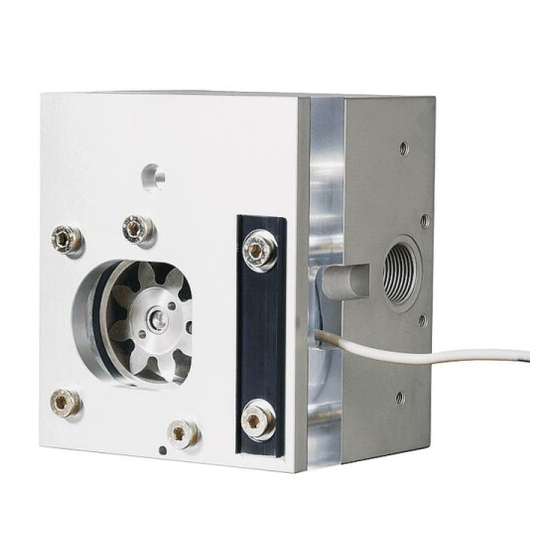
Versorgungsleitungen sowie zum Einstellen Bypass-Spindel der Bypass-Funktion zu achten. Kabelkanal-Abdeckung/Schildträger Verbindungsschraube für Modul- bauweise Abb. 1 SMD 1B / SMD 2 4.2 Montage Achtung! Schrankmontage Beim Herstellen der Montage- Die Montage der Mengendrosseln erfolgt von bohrungen ist unbedingt auf eventuell der Rückseite mittels 2 Schrauben (M 8x15). -
Page 13: Montagebohrungen
± braun NAMUR Betriebsdaten nach DIN 19234 Mitteleingangs- SMD3 Mittel- SMD1B+2 absperrmodul eingangs mit Spülanschluss Modul 8,2 V Abb. 3 Montage-Lochbild für SMD 1B / SMD 2 / SMD 3 1 KΩ 20 °C 1,8 mA Abb. 4 Anschlusskabel NAMUR-Schalter... -
Page 14: Kenngrößen Smd 1B
Seite 14 4. Montage 4.5 Kenngrößen SMD 1B Bauart......Drosselventil Einbaulage ......beliebig Werkstoff . -
Page 15: Kenngrößen Smd
4. Montage Seite 15 4.6 Kenngrößen SMD 2 Bauart......Drosselventil Einbaulage ......beliebig Werkstoff . -
Page 16: Kenngrößen Smd 3
Seite 16 4. Montage 4.7 Kenngrößen SMD 3 Bauart ......Drosselventil Einbaulage ......beliebig Werkstoff . -
Page 17: Funktionsweise
Korrekturen in der Schmierstoffzufuhr stellung der Drosselspindel und dem damit Drosselspindel bei laufender Maschine ausführbar sein sollen. verbundenen Volumenstrom. Zahnräder Radkammer NAMUR-Schalter Eingang Schmiermedium Ausgang Schmiermedium Abb. 5 Beispiel SMD 1B / SMD 2 Abb. 6 Beispiel SMD 1B / SMD 2... -
Page 18: Bypassfunktion
SMD 1B / SMD 2 SMD 1B / SMD 2 SMD 3 Sicherungsstift Drosselspindeln Sicherungsstift Sicherungsstift Ansicht Bypass-Spindel ca. 90 ° Ansicht ca. 90 ° ca. 180 ° Abb. 8 SMD 1B / SMD 2 / SMD 3 Bypass geschlossen Bypass-Spindel Bypass-Spindel... -
Page 19: Bypass Geöffnet (Servicestellung)
SMD 1B / SMD 2 SMD 1B / SMD 2 SMD 3 Drosselspindeln Ansicht Sicherungsstift Sicherungsstift Sicherungsstift Bypass-Spindel Ansicht ca. 90 ° ca. 90 ° ca. 180 ° Bypass-Spindel Bypass-Spindel Abb. 10 SMD 1B / SMD 2 / SMD 3 Bypass geöffnet... -
Page 20: Einstellung
siehe 951-130-310 (PGA 3) Grundeinstellung der Mengendrossel: SW 4 SMD 1B ....1 Impuls = 2,6 ml Einstellung der Drosselspindel SMD 2 ....1 Impuls = 9,3 ml • Drosselspindel (4) mittels Innensechs- SMD 3 ....1 Impuls = 39 ml kantschlüssel (3) solange verstellen, bis... -
Page 21: Inbetriebnahme
7. Inbetriebnahme Seite 21 7. Inbetriebnahme Achtung! Verschiedene Schmierstoffe dürfen nicht gemischt werden, da hierdurch Schäden auftreten können und eine aufwendige Reinigung des Produktes/ der Zentralschmieranlage notwendig werden kann. 7.1 Inbetriebnahme Vor der Inbetriebnahme des Produktes sind alle elektrischen und hydraulischen Anschlüsse zu überprüfen. -
Page 22: Außerbetriebnahme/Entsorgung
Gegen Erstattung der entstehenden beachten. entsorgt werden. Es sind die regionalen Kosten kann das Produkt auch von SKF Lubrication Systems Germany GmbH Vorschriften und Gesetze zur Entsor- Für die Wiederinbetriebnahme des Produktes gung von Schmierstoffen zu beachten. -
Page 23: Wartung
14.08.2002) zur Einstellung Gefahr! Grundsätzlich arbeiten die Mengendrosseln der Sicherungsstifte dienen Bei unsachgemäßer Betätigung der SMD 1B, SMD 2 und SMD 3 wartungsfrei. (Abb. 12). An Mengendrosseln, die Bypassfunktion kann es ggf. zur Jedoch können externe Verschmutzungs- nach dem oben genannten Termin Berührung mit heißem Schmieröl... -
Page 24: Bypassfunktion Öffnen (Servicestellung) (Auslieferungsdatum 14.08.2002)
(Der Dichtring (siehe stillstand durchzuführen. (ca.90°) drehen Abb. 14) verbleibt somit in seinem • Deckelschrauben (SMD 1B /SMD 2 = 4x, • Ansicht B Dichtsitz). Nach ca. 10 Sekunden muss SMD 3 = 6x) um je 1 Umdrehung lösen! ... - Page 25 Dichtring • Ansicht B Bypass-Spindel (SMD 1B/SMD 2) (5) entgegen Uhrzeigersinn bis Anschlag (ca.90°) drehen oder: • Bypass-Spindel (SMD 3) (4) entgegen Uhrzeigersinn bis Anschlag (ca. 180°) Ansicht A drehen Abb.14 SMD 1B/SMD 2 - mit Dichtring Abb.15 Bypass schließen...
-
Page 26: Bypassfunktion Öffnen (Servicestellung) (Ab Auslieferungsdatum 14.08.2002)
Uhrzeigersinn bis Anschlag (ca.90°) ein Minimum (maximal rasche Trop- drehen fenfolge) reduziert haben. Sollte dies • Deckelschrauben (SMD 1B/SMD 2 = 4x, oder: nicht der Fall sein, muss man davon SMD3 = 6x) um je 1 Umdrehung lösen! • Bypass-Spindel (SMD 3) im Uhrzeiger- ausgehen, dass die Bypass-Spindel ... -
Page 27: Bypassfunktion Schließen (Betriebs- Stellung- Neue Ausführung)
• Bypass-Spindel (SMD 3) (2) entgegen Zahnradkammer Uhrzeigersinn bis Anschlag (ca.180°) Ansicht A drehen Dichtring Abb. 18 Bypass schließen Nach der Umstellung der Bypass-Spindel drehen sich die Zahnräder der Zahnrad- durchlusskontrolle wieder => Betriebs- stellung. Abb. 17 SMD 1B/ SMD 2 - mit Dichtring... -
Page 28: Bypassfunktion Schließen (Betriebsstellung)
• Deckelschrauben lösen und mit Plexiglas- anziehen deckel entfernen Hilfsbohrungen • alte Zahnräder entfernen bzw. reinigen Anzugsmoment SMD 1B = 5 Nm • Zahnradkammer vorsichtig von Ablagerun- gen und Fremdkörpern reinigen Bypassfunktion schließen • gereinigte oder neue Zahnräder so einlegen, •... - Page 29 9. Wartung Seite 29 SMD 2 / SMD 3 Bypassfunktion öffnen • Bypassfunktion - wie unter Punkt 9.3 oder Die Einbaulage des Aluminiumrades ist 9.5 beschrieben- öffnen beliebig • Deckelschrauben lösen und mit Plexiglas- deckel entfernen Dichtring wechseln • alte Zahnräder entfernen bzw. reinigen •...
-
Page 30: Demontage/Montage Der Drosselspindel
6x) ansetzen deln (mit Ausnahme der zu wechseln- • Deckelschraube mittels Drehmoment- den Drosselspindel) zu schließen. schlüssel anziehen - siehe Abb. 22 Anzugsmoment Abb. 22 SMD 1B / SMD2 SMD 2 = 5 Nm, SMD 3 = 8 Nm... -
Page 31: Drosselspindel Ausführungen
Bestell- Nr. Umstellungssdatum Drosselspindel ( l/min) (Farbe) SMD 1A Feinstdrossel 0,05 bis 0,25 l/min Grün 44-1806-2022 bis 04/2006 SMD 1B Feinstdrossel 0,05 bis 1,0 l/min Blau 44-1806-2024 ab 04/2006 SMD 2 Feindrossel 0,1 bis 4,0 l/min 44-1806-2018 SMD 2 Grobdrossel... -
Page 32: Störung, Ursache Und Beseitigung
Seite 32 10. Störung, Ursache und Beseitigung Störung, Ursache und Beseitigung 10.1 Inbetriebnahmestörungen Störung Ursache Beseitigung Störung am Überwachungsgerät (IPM 12 oder Siehe Bedienungsanleitung „Überwachungs- PGA 3 Mobil) system VARIOLUB für Mengendrossel- schmieranlagen“ 951-130-300 (PGA 3), Kapitel 6 Keine Impulse, Auslesen der Istwerte fehlerhaft Zu hohe oder zu niedrige Spannungsversorgung Siehe Bedienungsanleitung „Überwachungs- des Überwachungsgerätes... -
Page 33: Zubehör
11. Zubehör Seite 33 11. Zubehör fein grob fein D2F/G grob fein grob... - Page 34 Mengendrossel (2 x Grobdrosseln) 24-2581-2657 24-2581-2617 Mengendrossel (1x Fein-Drosselspindel (oben) SMD 2 D2F/G 24-2581-2588 24-2581-2616 und 1 x Grob-Drosselspindel (unten)) SMD 1B/SMD2 Mittelelement komplett 24-1503-2103 24-2581-2104 SMD 1B/SMD2 Absperr-Mittelelement komplett 24-1503-2102 auf Anfrage Verschlussschraube G 3/4 DIN 908 (1.1/16-12 UN) 95-0034-0908 24-1855-2029...
-
Page 35: Ersatzteile
12. Ersatzteile Seite 35 Ersatzteile Eigenmächtiger Umbau und Ersatz- teilherstellung Umbau oder Veränderungen der Geräte sind nur nach Absprache mit dem Hersteller zulässig. Originalersatztei- le und vom Hersteller freigegebenes Zubehör dienen der Sicherheit. Die Verwendung anderer Teile hebt die Haftung für die daraus entstehenden Folgen auf. - Page 36 Seite 36 12. Ersatzteile Bestell-Nr. Bestell Nr. Bezeichnung Ausführung Ausführung Gewinde BSPP Gewinde UN/UNF SMD 1B (SMD 1A bis 04/2006) Ersatzteilsatz 24-9909-0184 24-9909-0184 SMD 2 Ersatzteilsatz 24-9909-0178 24-9909-0178 SMD 3 Ersatzteilsatz 24-9909-0179 24-9909-0179 SMD 1A / 1B / SMD 2...
- Page 37 Seite 37...
- Page 38 Trotzdem kann keine Haftung für Verluste oder Schäden irgendwelcher Art übernommen werden, die sich mittelbar oder unmittelbar aus der Verwendung der hierin enthaltenen Informationen ergeben. Alle Produkte von SKF dürfen nur bestimmungsgemäß, wie in dieser Montageanleitung mit dazugehö- riger Betriebsanleitung beschrieben, verwendet werden. Werden zu den Produkten Montage-/ Betriebsanleitungen geliefert, sind diese zu lesen und zu befolgen.
- Page 39 Components Lifecycle Manual Flow meter SMD 1B, SMD 2, SMD 3...
- Page 40 Page 40 Service © SKF Lubrication Systems Germany GmbH If you have technical questions, please contact This documentation is protected by copyright. the following addresses: SKF Lubrication Systems Germany GmbH re- serves all rights, including those to the photo- SKF Lubrication Systems Germany GmbH mechanical reproduction, duplication, and dis- tribution by means of special procedures (e.g.,...
- Page 41 4.3 Mounting holes 9.3 Set to bypass mode (service position) 4.4 NAMUR switch connection (up to 14 August 2002) 4.4 Technical data SMD 1B 9.4 Reset to normal operation (operating 4.5 Technical data SMD 2 position) (up to 14 August 2002)
-
Page 42: Overview
Assembly instructions Page 42 Overview SMD 1B SMD 2 SMD 3 Bypass mode activation Page 62 to 66 Installation Page 50 Throttle screw change Page 69 Gear change Page 67 NAMUR switch connection Page 51 Throttle screw change Page 69... -
Page 43: Explanation Of Symbols And Signs
Explanation of symbols Page 43 Explanation of symbols and signs You will ind these symbols, which warn of Instructions placed directly on the machines/ speciic dangers to persons, material assets, or grease lubrication pump units, such as: the environment, next to all safety instructions Arrow indicators L abels for luid connections in these operating instructions. You are responsible! Please heed these instructions and proceed must be followed and kept in fully legible with special care in such cases. -
Page 44: Safety Instructions
Note that the assembly instructions Floe meters of SKF´s SMD series are designed scribed product is incorporated. Such persons form part of the product and must... -
Page 45: Electric Shock Hazard
1. Safety instructions Page 45 1.3 Electric shock hazard 1.4 System pressure hazard Electrical connections for the described product Lubrication systems are pressurized may only be established by qualified and during operation. Centralized lubrication trained personnel authorized to do so by the systems must therefore be depressur- operator, and in observance of the local condi- ized before starting assembly, main-... -
Page 46: Lubricants
SKF Lubrication Systems Germany quantity of lubricant is provided to the GmbH. lubrication point. The lubrication point... -
Page 47: Approved Lubricants
The product described here can be operated You can request an overview of the lubricant using lubricants that meet the specifications in tests offered by SKF Lubrication Systems the technical data. Depending on the product Germany GmbH from the company's Service design, these lubricants may be oils, fluid greases, or greases. -
Page 48: Lubricants And Environment
2. Lubricants Page 48 2.4 Lubricants and the environment 2.5 Lubricant hazards Lubricants can contaminate soil and Centralized lubrication systems must al- Warning! bodies of water. Lubricants must be ways be free of leaks. Leaking lubricant Follow the safety instructions on the properly used and disposed of. -
Page 49: Transport, Delivery, And Storage
Storage temperature: 10 - 40°C pleteness according to the shipping documents. Light: avoid direct sun or UV exposure and The packaging material must be preserved until any discrepancies are resolved. SKF Lubrication Systems Germany GmbH prod- ucts are subject to the following storage conditions:... -
Page 50: Installation
/ plate holder function. connecting screw for modular system 4.2 Installation Fig. 1 SMD 1B / SMD 2 Attention! Cabinet installation When drilling the mounting holes, The low meters are mounted with 2 bolts always pay attention not only to supply (M 8x15) which are screwed in from to rear. -
Page 51: Mounting Holes
NANUR operating data to DIN 19234 SMD3 Inlet SMD1A+2 inlet connetion connetion block, with shut-off block flushing port 8,2 V Fig. 3 Mounting pattern for SMD 1B / SMD 2 / SMD 3 1 KΩ 20 °C 1,8 mA Fig. 4 NAMUR switch connection cable... -
Page 52: Technical Data Smd 1B
4. Installation Page 52 4.4 Technical data SMD 1B Type ..............throttle valve Mounting position ..........any Material .............housing = aluminum, anodized; cover = plastic, clear; gears = plastic Inlet ports ............G 3/4 ) (1.1/16-12 UN Outlet ports ............G 3/8 ) (9/16-18 UNF Ambient temperature range ......0 °C to + 70 °C... - Page 53 4. Installation Page 53 4.5 Technical data SMD 2 Type ..............throttle valve Mounting position ..........any Material .............housing = aluminum, anodized; cover = plastic, clear; gears = plastic Inlet ports ............G 3/4 ) (1.1/16-12 UN Outlet ports ............G 3/8 ) (9/16-18 UNF Ambient temperature range ......0 °C to + 70 °C Number of outlets per block ......2 Weight ...............1.57 kg...
- Page 54 4. Installation Page 54 4.6 Technical data SMD 3 Type ..............throttle valve Mounting position ..........any Material .............housing = aluminum, anodized; cover = plastic, clear; gears =plastic Inlet ports ............G 3/4 ) (1.1/16-12 UN Outlet ports ............G 3/8 ) (9/16-18 UNF Ambient temperature range ......0 °C to + 70 °C Number of outlets per block ......1 Weight ...............4.31kg...
-
Page 55: Description
Throttle screw associated therewith. gear chamber gears NAMUR switch Inlet port lubricant Outlet port lubricant Fig. 5 Example of SMD 1B / SMD 2 Fig. 6 Example of SMD 1B / SMD 2... -
Page 56: Bypass Mode
SMD 3 throttle screw locking pin locking pin View B locking pin bypass valve approx. 90 ° approx. 90 ° approx. View A bypass valve bypass valve 180 ° Fig. 8 SMD 1B / SMD 2 / SMD 3 Bypass closed... -
Page 57: Bypass Opened (Service Position)
SMD 3 throttle screw locking pin locking pin View B locking pin bypass valve View A approx. 90 ° approx. 90 ° approx. 180 ° bypass valve bypass valve Abb.10 SMD 1B / SMD 2 / SMD 3 Bypass opened... -
Page 58: Adjustment
Mobile PGA 3 (Programming and WAF 4 Display Unit) See 951-130-310 (PGA 3), Chapter 5.3 SMD 1B ....1 pulse = 2.6 ml ”Reading out the speciied and actual values” SMD 2 ....1 pulse = 9.3 ml Adjusting the throttle screw SMD 3 ....1 pulse = 39 ml •... -
Page 59: Operation
7. Operating Page 59 7. Operation Caution! Different lubricants must not be mixed together. Doing so can cause damage and require extensive cleaning of the compact unit/centralized lubrication system. To prevent confusion, we recommend that you it an adhesive label on the reservoir with the information indicating the lubricant to be used on the lubricant reservoir. -
Page 60: Shutdown/Disposal
'Installation' and 'Startup’ of this owner’s SKF Lubrication Systems Germany GmbH will manual. take back the product and arrange for its legal disposal. Costs to the customer will be limited... -
Page 61: Maintenance
That is why attention must be paid to So only loosen the bypass valve locking the permissibility of the lushing medium when pin by the amount speciied. ar (9.3 / meters (SMD 1B or SMD 2). the low meter is cleaned with such a luid. SKF 9.4), the bypass valve may disengage Please note! should be consulted if necessary. When the bypass function is active, a 9.2 Bypass mode... -
Page 62: Set To Bypass Mode (Service Position)
The oil in the gear chamber is under (4) or (5) pressure. The oil can escape from the • Loosen cover bolts (SMD 1B /SMD 2 = 4x, • View A gear chamber if the cover bolts are SMD 3 = 6x) 1 turn each! As a result of the drop in pressure a small... - Page 63 (4) clockwise until the stop is reached View B (approx. 90°) o-ring • View B seal Turn the bypass valve (SMD 1B/SMD 2) (5) counterclockwise until the stop is reached (approx. 90°) • Turn the bypass valve (SMD 3) (4) counterclockwise until the stop is reached View A (approx.
-
Page 64: Set To Bypass Mode (Service Position) (Up To 14 August 2002)
(2) counterclockwise until the stop is reached (approx.90°). oil from the gear chamber must have • Loosen the cover bolts (SMD 1B /SMD 2 • View B dropped to a minimum (a fast string = 4x, SMD 3 = 6x) 1 turn each! Turn the bypass valve (SMD 1B/SMD 2) of drops at the most). -
Page 65: Reset To Normal Operation (Operating Position - New Version)
• Use an alle key (1) to tighten the locking pin (DIN 915) (2) by turning it clockwise 1 revolution After turning the bypass valve the gears of the gear wheel-type low indicator will Fig. 17 SMD 1B/ SMD 2 - with o-ring seal spin again => operating position. -
Page 66: Reset To Normal Operation
Remove or clean existing gears • Carefully clean the gear chamber of depo- Tightening torque sits and particles SMD 1B = 5 Nm auxiliary holes • Insert the cleaned or new gears so that the auxiliary holes point to of the cover Reset to normal operation ... - Page 67 9. Maintenance Page 67 SMD 2 / SMD 3 Set to bypass mode • Set to bypass mode - as described in 9.3 closed gear face or 9.5 Change gasket • If necessary, replace the low meter • Loosen cover bolts and remove together with plastic cover housing’s o-ring seal closed gear face •...
-
Page 68: Dismantling/Assembly Of Throttle Screws
Tightening torques - see Fig. 22 SMD 2 = 5 Nm • Close ( by turning clockwise) all the thrott- SMD 3 = 8 Nm le screws on the low meter block with a Fig. 22 SMD 1B / SMD2 an allen key (1) -
Page 69: Throttle Screw Performance
9. Maintenance Page 69 9.9 Throttle screw performance Type Designation Rated low Marking Order no. Conversion date throttle screws ( l/min) (Color) (SMD 1A superine throttles 0,05 bis 0,25 l /min green 44-1806-2022) until 04/2006 SMD 1B superine throttles 0,05 bis 1,0 l/min blue 44-1806-2024 from 04/2006 SMD 2 ine throttles 0,1 bis 4,4 l/min red 44-1806-2021 SMD 2... -
Page 70: Troubleshooting Procedures
10. Troubleshooting Procedures Maintenance Page 70 10. Troubleshooting Procedures 10.1 Startup faults Malfunction Cause Remedy Malfunctioning monitoring device (IPM 12, See operating instructions for ”VARIOLUB monitoring system for low meter lubrication and Mobile-PGA 3 systems” 951-130-300 (PGA 3), Chapter 6. No pulses, faulty readout of actual values. Supply of voltage to monitoring unit too high or See operating instructions for ”VARIOLUB“... -
Page 71: Order List
11. Order List Page 71 11. Order List fine fine coause D2F/G fine coause coause... - Page 72 UN/UNF thread SMD 3 Flow meter 24-2581-2592 24-2581-2693 (SMD 1A Flow meter (2 superfine throttle screws) 24-2581-2598 24-2581-2630) SMD 1B Flow meter (2 superfine throttle screws) 24-2581-2650 24-2581-2651 SMD 2 Flow meter (2 fine throttle screws) 24-2581-2586 24-2581-2615 SMD 2...
-
Page 73: Spare Parts
12. Spare Parts Page 73 12. Spare Parts Unauthorized conversion and fabrica- tion of spare parts The equipment may be converted or modiied only after consultation with the manufacturer. Original spare parts and released accessories by the manuf- acturer provide safety. The use of other parts will nullify any liability for conse- quences arising therefrom. - Page 74 12. Spare Parts Page 74 Order No. Order No. Speciication Speciication Type Designation BSPP thread UN/UNF thread SMD 1B(SMD1A, until 04/2006) Spare parts kit 24-9909-0184 24-9909-0184 SMD 2 Spare parts kit 24-9909-0178 24-9909-0178 SMD 3 Spare parts kit 24-9909-0179 24-9909-0179 SMD 1A;...
- Page 75 Page 75...
- Page 76 All SKF products may be used only for their intended purpose as described in these assembly instruc- tions with associated operating instructions. If assembly/operating instructions are supplied together with the products, they must be read and followed.
- Page 77 Composants Cycle De Vie Manuel Débitmètres SMD 1B, SMD 2, SMD 3...
- Page 78 Page 78 Service © SKF Lubrication Systems Germany GmbH Pour toutes questions techniques, vous pouvez Cette documentation est protégée par les vous adresser à : droits d'auteur. Tous les droits sont réservés. La reproduction photomécanique, la copie et la SKF Lubrication Systems Germany GmbH diffusion, même partielle, de cette documenta-...
- Page 79 (modèle livré jusqu'au 4.3 Plan de pose 14.08.2002) 4.4 Connexion du détecteur NAMUR 9.4 Fermeture du by-pass (service normal) 4.5 Caractéristiques SMD 1B (modèle livré jusqu'au 14.08.2002) 4.6 Caractéristiques SMD 2 9.5 Ouverture du by-pass (position de 4.7 Caractéristiques SMD 3...
-
Page 80: Description
Description Page 80 Description SMD 1B SMD 2 SMD 3 mise en place du by-pass pages 102 à 103 montage page 88 changement des tiges d'étranglement page 107 changement des engrenages page 105 connexion du détecteur NAMUR page 89 changement des tiges d'étranglement... -
Page 81: Pictogrammes Et Messages D'information
Page 81 Signification des pictogrammes Pictogrammes et messages d'information Vous trouvez ces pictogrammes avec toutes Les informations apposées directement sur la machine/le groupe motopompe de lubriica- les consignes de sécurité, qui signalent des dangers particuliers pour les personnes, les tion, comme par exemple : Le sens de rotation indiqué par une lèche Vous êtes responsables ! biens ou l'environnement. -
Page 82: Consignes De Sécurité
1. Consignes de sécurité Page 82 1. Consignes de sécurité L'utilisateur du produit décrit doit s'assu- En complément de la notice, il est im- 1.2 Personnel autorisé rer que toutes les personnes participant portant de respecter toutes les directi- au montage, à la mise en service, à ves légales ou généralement applicables Seul un personnel qualifié... -
Page 83: Dangers Relatifs Au Courant Électrique
1. Consignes de sécurité Page 83 1.3 Dangers relatifs au courant électrique 1.4 Dangers relatifs à la pression du système Les installations de lubriication peuvent Seul le personnel qualifié, ayant eu une forma- tion spéciale correspondante et étant autorisé être sous pression. Pour cette raison, les installations de lubriication centra- par l'utilisateur, peut procéder au branchement électrique du produit décrit dans le respect des... -
Page 84: Lubriiants
2. Lubriiants 2.2 Sélection des lubriiants 2.1 Généralité Tous les produits SKF Lubrication qués par SKF Lubrication Systems Germany Il faut respecter les consignes du fabricant Systems Germany GmbH doivent être GmbH est incompatible avec l'emploi de gaz, de la machine en ce qui concerne les lubriiants à utiliser. -
Page 85: Lubriiants Autorisés
Différents lubriiants ne peuvent pas être les élastomères. mélangés ensemble, car cela pourrait Pour toutes autres questions sur les lubri- fiants, vous pouvez prendre contact avec SKF causer des dommages et nécessiter Lubrication Systems Germany GmbH. Il est le nettoyage complet du produit/de l'installation de lubriication. Ain d'éviter également possible de tester dans nos propres... - Page 86 2. Lubrifiants Page 86 2.4 Lubriiants et environnement 2.5 Dangers liés aux lubriiants Attention ! Danger ! Attention ! Les lubriiants peuvent polluer le sol et Les installations de lubriication centra- Il faut respecter les consignes de sécu- l'eau. Les lubriiants doivent être utilisés rité décrites dans la iche de données de lisée doivent absolument être étanches. Une fuite de lubriiant représente sécurité du lubriiant. et évacués dans le respect des règles. Les consignes et réglementations régio- une source de danger.
-
Page 87: Transport, Livraison Et Stockage
UV, protéger contre des sour- mécaniques. Conservez le matériel d'emballage jusqu'à ce ces de chaleur éventuelles. que toute irrégularité éventuelle soit éclaircie. Il faut respecter les conditions de stockage sui- vantes pour les produits de SKF Lubrication Systems Germany GmbH :... -
Page 88: Montage
: respecter les distances de sécurité, ainsi que les directives locales portant sur le SMD 1B ; SMD 2 ; SMD 3 . => 17 Nm montage et la prévention des accidents. Fig. 2 SMD 3... -
Page 89: Plan De Pose
SMD3 SMD1B+2 d'entrée d'isolation avec intermédiaire raccordement de rinçage 8,2 V Fig. 3 Plan de pose des SMD 1B / SMD 2 / SMD 3 1 KΩ T = 20 °C à 1,8 mA Fig. 4 de raccordement détecteur NAMUR... -
Page 90: Caractéristiques Smd 1B
Page 90 4. Montage 4.5 Caractéristiques SMD 1B Type ......vanne d'étranglement Position de montage . - Page 91 Page 91 4. Montage 4.6 Caractéristiques SMD 2 Type ....... vanne d'étranglement Position de montage .
- Page 92 Page 92 4. Montage 4.7 Caractéristiques SMD 3 Type ......vanne d'étranglement Position de montage .
-
Page 93: Fonctionnement
NAMUR entrée lubrifiant sortie lubrifiant Fig. 5 Exemple SMD 1B / SMD 2 Fig. 6 Exemple SMD 1B / SMD 2... -
Page 94: Fonction De By-Pass
90 ° env. 90 ° env. 180 ° Fig. 8 SMD 1B / SMD 2 / SMD 3 by-pass fermé tige de by-pass tige de by-pass... -
Page 95: By-Pass Ouvert (Position De Maintenance)
SMD 1B / SMD 2 SMD 3 tige d'étranglement goupille de sécurité tige de by-pass env. 90 ° env. 90 ° env. 180 ° tige de by-pass tige de by-pass Fig. 10 SMD 1B / SMD 2 / SMD 3 by-pass ouvert... -
Page 96: Réglage
5.1.2 «Ajustement valeur réelle et valeur souhaitée IPM-12 » Réglage de base du débitmètre SW 4 SMD 1B ..... 1 impulsion = 2,6 ml Lecture des valeurs souhaitée et réelle SMD 2 ....1 impulsion = 9,3 ml •... -
Page 97: Mise En Service
Page 97 6. Réglage /7. Mise en service 7. Mise en service du PGA 3 portable (1) corresponde à la Attention ! Différents lubriiants ne peuvent pas valeur souhaitée. En tournant la tige d'étranglement dans être mélangés ensemble, car cela pour- le sens horaire, le débit est réduit, et en la rait causer des dommages et nécessiter tournant dans le sens anti-horaire, il sera le nettoyage complet du produit/de... -
Page 98: Mise Hors Service/Élimination
Pour une remise en service du produit, il faut tion contre paiement des frais. respecter les consignes des chapitres « Montage ». SKF Lubrication Systems Germany GmbH reprend également les produits et se charge de leur élimination contre paiement des frais. -
Page 99: Maintenance
9. Maintenance 9. Maintenance sous la forme de deux oriices de 9.1 Généralités Danger ! En principe, les débitmètres SMD 1B, SMD passage se trouvent sur le couvercle Lors d'une opération inappropriée 2 et SMD 3 ne nécessitent aucune mainte- en plastique, permettant le réglage de la fonction de by-pass, l'utilisa- des goupilles de sécurité (ig. 12) -
Page 100: Ouverture Du By-Pass (Position De Maintenance)
Utiliser un tournevis (3) sur la tige de by-pass (4) ou (5) les vis du couvercle avec prudence (1 tour), • Desserrer les vis du couvercle (SMD 1B / • Vue A Tourner la tige de by-pass (SMD l'huile peut s'échapper de la chambre d'engre-... -
Page 101: Fermeture Du By-Pass (Service Normal) (Modèle Livré Jusqu'au 14.08.2002)
(4) ou (5) vis du couvercle • Vue A couvercle en plexiglas vue B Tourner la tige de by-pass (SMD 1B/SMD chambre d'engrenages 2) (4) dans le sens des aiguilles d'une montre jusqu'à la butée (env. 90°) bague •... - Page 102 (env. 90°) minimum (au plus un égouttement • Desserrer les vis du couvercle (SMD 1B / Autre possibilité : rapide). Si ce n'est pas le cas, il faut SMD 2 = 4x, SMD 3 = 6x) d'un tour cha- •...
-
Page 103: Nouveau Modèle)
Utiliser une clé pour vis à six pans creux (1) sur la tige de by-pass (2) ou (3) tiges d'étranglement • Vue A Tourner la tige de by-pass (SMD 1B/SMD 2) (2) dans le sens des aiguilles d'une vue B vue A montre jusqu'à la butée (env.90°) Fig. -
Page 104: Démontage/Montage Des Engrenages
étrangers Couple de serrage SMD 1B = 5 Nm • Replacer les engrenages nettoyés ou nou- Fig. 19 SMD 1B veaux, de telle façon que les trous auxiliai- Fermeture de la fonction de by-pass res regardent vers le couvercle •... - Page 105 Page 105 9. Maintenance SMD 2 / SMD 3 Ouverture de la fonction de by-pass • Ouvrir la fonction de by-pass - comme décrit que doit être mis en place de telle façon qu'il au point 9.3 ou 9.5 repose contre le détecteur NAMUR monté •...
-
Page 106: Démontage/Montage De La Tige D'étranglement
Veiller à ce que la bague d'étanchéité soit d'étranglement (à l'exception de celle mise en place correctement qui doit être changée). • Mettre les vis du couvercle (SMD2 = 4x, - voir ig. 22 Fig. 22 SMD 1B / SMD2 SMD3 = 6x) -
Page 107: Tableau Des Tiges D'étranglement
Page 107 9. Maintenance 9.9 Tableau des tiges d'étranglement Type Modèle Débit nominal Identiication Référence Date de changement tige d'étranglement ( l/min) (couleur) SMD 1A étranglement très in 0,05 à 0,25 l/min vert 44-1806-2022 jusqu'au 04/2006 SMD 1B étranglement très in 0,05 à 1,0 l/min bleu 44-1806-2024 après le 04/2006 SMD 2 étranglement in 0,1 à 4,0 l/min rouge 44-1806-2018 SMD 2 étranglement grossier 4,0 à... -
Page 108: Défaut, Cause Et Remède
Page 108 10. Défaut, cause et remède Défaut, cause et remède 10.1 Défauts de mise en service Défaut Cause Remède Défaut au niveau de l'appareil de contrôle (IPM Voir la notice de mise en service et mainte- 12 ou PGA 3 portable) nance «... -
Page 109: Accessoires
Page 109 11. Accessoires 11. Accessoires grossier точный грубый точный D2F/G grossier grossier грубый точный грубый... - Page 110 24-2581-2588 24-2581-2616 et 1 x tige d'étranglement grossier (dessous)) SMD 1B/SMD2 élément intermédiaire, complet 24-1503-2103 24-2581-2104 SMD 1B/SMD2 élément intermédiaire d'isolation, complet 24-1503-2102 sur demande bouchon de fermeture G 3/4 DIN 908 (1.1/16-12 UN) 95-0034-0908 24-1855-2029 bague d'étanchéité A27x32 DIN 7603 Cu 95-2721-7603 plaque signalétique VARIOLUB...
-
Page 111: Pièces De Rechange
Page 111 12. Pièces de rechange Pièces de rechange Modiication et fabrication de pièces de rechange arbitraires La transformation ou des modiica- tions de l'appareil ne sont permise qu'après consultation avec le fabricant. Les pièces de rechange d'origine et les accessoires autorisés par le fabri- cant servent à... - Page 112 12. Pièces de rechange Référence Référence Type Désignation modèle modèle iletage BSPP iletage UN/UNF SMD 1B (SMD 1A jusqu'au 04/2006) jeu de pièces de rechange 24-9909-0184 24-9909-0184 SMD 2 jeu de pièces de rechange 24-9909-0178 24-9909-0178 SMD 3 jeu de pièces de rechange...
- Page 113 Page 113...
- Page 114 Tous les produits SKF doivent être employés dans le strict respect des consignes telles que décrites dans cette notice de montage et la notice de mise en service correspondante. Dans le cas où des notices de montage/de mise en service sont fournies avec les produits, elles doivent être lues attentivement et respectées.
Need help?
Do you have a question about the SMD 1B and is the answer not in the manual?
Questions and answers