Table of Contents
Advertisement
Quick Links
BEDIENUNG UND INSTALLATION
OPERATION AND INSTALLATION
UTILISATION ET INSTALLATION
BEDIENING EN INSTALLATIE
USO E INSTALLAZIONE
OBSLUHA A INSTALACE
OBSŁUGA I INSTALACJA
KEZELÉS ÉS TELEPÍTÉS
ЭКСПЛУАТАЦИЯ И УСТАНОВКА
KÄYTTÖ JA ASENNUS
BETJENING OG INSTALLATION
Fernbedienung | Remote control | Commande à distance | Afstandsbediening | Telecomando | Dálkové ovládání | Termostat
pokojowy | Távirányító | Дистанционное управление | Kauko-ohjaus | Fjernbetjening | Fjärrkontroll | Daljinski upravljalnik |
Diaľkové ovládanie
» FET
HANDHAVANDE OCH INSTALLATION
UPRAVLJANJE IN INSTALACIJA
OBSLUHA A INŠTALÁCIA
Advertisement
Table of Contents

Related Manuals for STIEBEL ELTRON FET


Summary of Contents for STIEBEL ELTRON FET
- Page 1 BETJENING OG INSTALLATION OBSLUHA A INŠTALÁCIA Fernbedienung | Remote control | Commande à distance | Afstandsbediening | Telecomando | Dálkové ovládání | Termostat pokojowy | Távirányító | Дистанционное управление | Kauko-ohjaus | Fjernbetjening | Fjärrkontroll | Daljinski upravljalnik | Diaľkové ovládanie » FET...
-
Page 2: Operation
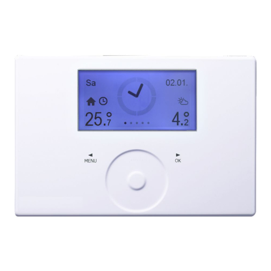
2 Weather 3. Appliance description 3 Outside temperature 4 Menu level The FET digital remote control enables convenient operation 5 Time of one heating zone. The remote control measures the relative 6 Room temperature / relative humidity humidity and room temperature. -
Page 3: Touch-Wheel
OPERATION Operation 4.4 Sensor keys Symbols Inside temperature Note Symbol for inside temperature If a key is touched for too long, the device does not respond. f Tap the sensor keys only briefly to initiate the re- Time program quired action. If the room temperature has been changed for a spe- cific period, the clock symbol is displayed. -
Page 4: Program Menus
The temperature for setback mode (ECO temperature) is set If summer mode is active on the heat pump manager, by the heat pump manager (see SETTINgS / dHW / dHW TEM- settings made at the FET remote control will not have PERATuRES / ECO TEMPERATuRE in the heat pump manager). any effect. - Page 5 OPERATION Menu 5.1.3 COMFORT WARMWASSER In this menu, you can permanently change the comfort tem- perature for the room. 35° COMFORT KOMFORT 20° f Touch "MENu" or "OK" to switch to the dHW menu. The display shows the currently set value. f Keep your finger on the Touch-Wheel.
- Page 6 OPERATION Menu f Touch "MENu" or "OK" to switch to the SETTINgS menu. Note The display shows a padlock symbol. Set temperatures can be adjusted on the device via f Keep your finger on the Touch-Wheel. A circle appears. SETTINgS / HEATINg / COMFORT TEMPERATuRE and ECO TEMPERATuRE or on the heat pump manager via SETTINgS / HEATINg / HEATINg CIRCuIT / COMFORT TEMPERATuRE and ECO TEMPERATuRE.
-
Page 7: Installation
INSTALLATION Troubleshooting INSTALLATION RELATIVE HUMIDITY CORRECTION … …„ Note Set this parameter when the remote control's humidity sensor is not measuring the relative humidity correctly Safety due to the installation location. Only a qualified contractor should carry out installation, com- Select RELATIVE HuMIdITY CORRECTION to correct the dis- missioning, maintenance and repair of the appliance. -
Page 8: Electrical Connection
CAN-High WPM heat pump manager For securing to a wall, we recommend using a flush box which FET remote control can hold this part of the CAN bus cable. f Make sure that the screws supporting the flush box are arranged either vertically or horizontally opposite one another. -
Page 9: Specification
INSTALLATION | guARANTEE | ENVIRONMENT ANd RECYCLINg Commissioning 11. Commissioning 11.1 Initial start-up Once the device has been wired to the heat pump manager, the commissioning wizard starts up. f Select the heating circuit for which the device is responsi- ble. - Page 10 STIEBEL ELTRON GmbH & Co. KG tecalor GmbH Dr.-Stiebel-Str. 33 | 37603 Holzminden Lüchtringer Weg 3 | 37603 Holzminden Tel. 05531 702-0 | Fax 05531 702-480 Tel. 05531 99068-95700 | Fax 05531 99068-95712 info@stiebel-eltron.de info@tecalor.de www.stiebel-eltron.de www.tecalor.de 4 < A M H C M O = c f h j f a >...
Need help?
Do you have a question about the FET and is the answer not in the manual?
Questions and answers