
Related Manuals for H3C RPS1600-A


Summary of Contents for H3C RPS1600-A
- Page 1 H3C RPS1600-A User Manual New H3C Technologies Co., Ltd. http://www.h3c.com Document version: 6PW103-20180126...
- Page 2 Copyright © 2011-2018, New H3C Technologies Co., Ltd. and its licensors All rights reserved No part of this manual may be reproduced or transmitted in any form or by any means without prior written consent of New H3C Technologies Co., Ltd. Trademarks H3C,...
- Page 3 Documentation feedback You can e-mail your comments about product documentation to info@h3c.com. We appreciate your comments...
-
Page 4: Table Of Contents
Installation ·············································· 10 Precautions ·································································· 10 Installing the RPS1600-A ················································· 11 Installing the RPS1600-A in a 19-inch rack ····················· 12 Installing the RPS1600-A on a workbench ······················ 17 Connecting the grounding cable ········································ 17 ... -
Page 5: Product Overview
PD works properly, both the RPS1600-A and the PD’s power supply can supply power to implement load sharing; when the power supply of the PD fails, only the RPS1600-A works to ensure uninterrupted operation of the PD. -
Page 6: Front Panel
NOTE: As optional parts for the RPS1600-A, different types DC output cables are available depending on the requirement of the powered device. For details about the DC output cables, please consult H3C marketing or customer service staff. Front panel The RPS1600-A has two power module slots, allowing two power modules to work in parallel, one of which is provided by default and the other is optional. -
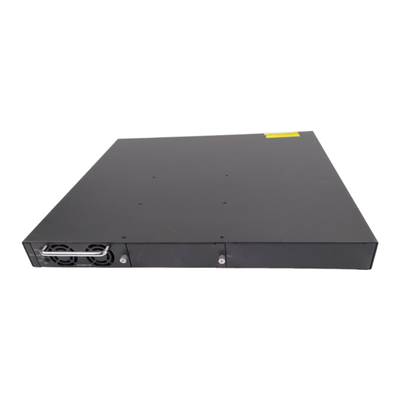
Page 7: Rear Panel
Rear panel Figure 2 Rear panel of the RPS1600-A (1) AC input for power module 1 (2) AC input for power module 2 (3) 25-A output reset buttons (4) 25-A DC outputs (5) 8-A DC outputs (6) Grounding screw (7) Fuses for the 8-A DC outputs NOTE: •... -
Page 8: Technical Specifications And Performance
NOTE: The design of this product complies with environmental protection requirements. Be sure to observe the relevant local laws and regulations when storing, using, or disposing of this product. The RPS1600-A supports a variety of protection features, as shown Table... - Page 9 Table 2 Protection features of the RPS1600-A Item Description When the input voltage exceeds 295 ± 5 VAC, the unit executes an over-voltage protection shutdown and displays an alarm through the Input alarm LED. over-voltage protection When the input voltage comes down to 275 ± 5 VAC, the unit automatically recovers and clears the alarm.
-
Page 10: Ad162M56-1M1/Ad162M56-1M1A Power Module
Item Description A protection action of one output does not affect any other. Per-output • For a 25-A output, press the reset button to over-current protection and clear the condition; short-circuit • For an 8-A output, check the corresponding protection fuse, and replace the fuse if it was blown to clear the condition. -
Page 11: Front Panel Of The Power Module
Front Panel of the power module Figure 3 Front panel of the power module (1) Handle (2) Run LED (3) Alarm LED (4) Fault LED (5) Captive screw LEDs description Table 3 LEDs description Color Status Fault description • An AC mains problem has occurred. -
Page 12: Output Power Distribution
CAUTION: • When the run LED is off, check whether an AC power input failure occurs. • When the alarm LED is on, check whether an input over-voltage or under-voltage, an output over-current, or an over-temperature condition occurs. • When the fault LED is on, check whether an output over-voltage or short-circuit condition or a fan fault occurs. - Page 13 WARNING! The RPS1600-A can provide power supply to multiple PDs simultaneously. Use one or two power modules depending on the power consumption of the PDs. Make sure that: • The system power consumption of each PD does not exceed the maximum output power of the corresponding DC output;...
-
Page 14: Installation
RPS1600-A for heat dissipation. Never block the air intake and outlet of the RPS1600-A. (The air intake of the RPS1600-A is located on the front panel of the AD162M56-1M1/ AD162M56-1M1A. -
Page 15: Installing The Rps1600-A
Note: Dust particle diameter ≥ 5 µm Table 6 Limits on harmful gas concentration Limit (mg/m 0.006 0.05 0.01 Installing the RPS1600-A The RPS1600-A can be installed either in a 19-inch standard rack or on a workbench. -
Page 16: Installing The Rps1600-A In A 19-Inch Rack
Installing the RPS1600-A in a 19-inch rack WARNING! Disconnect the AC power before installation. For security, unplug the power modules first, install the cabinet to the rack, and then insert the power modules. Mounting brackets Figure 4 Front and rear mounting brackets... - Page 17 Install the RPS1600-A by using front and rear mounting brackets Follow these steps to install the RPS1600-A by using front and rear mounting brackets: Wear an ESD-preventive wrist strap (make sure it makes good skin contact and is well grounded), and check the grounding and stableness of the rack.
- Page 18 (1) Weight-bearing screws (2) Holes for mounting the weight-bearing screws (select one as needed) (3) Front panel of the RPS1600-A (4) Front mounting bracket In accordance with the RPS unit installation position in the rack, fix the rear mounting brackets to the rear square-holed posts by...
- Page 19 Fix the front mounting brackets to the front square-holed posts of the rack by using M6 screws and cage nuts (user supplied). Make sure that the RPS1600-A is securely fixed with the front and rear mounting brackets on the rack, as shown in...
- Page 20 Figure 8 Install the RPS1600-A to the rack by using front and rear mounting brackets (1) Weight-bearing screw (2) Rear mounting bracket (3) Front panel of the RPS1600-A (4) M6 screw (5) Front mounting bracket (6) Front post of the rack...
-
Page 21: Installing The Rps1600-A On A Workbench
Peel off the stickers on the supplied foot pads and paste the foot pads into the dents on the chassis bottom. Turn over the RPS1600-A and place it on the workbench. Make sure that the workbench is sturdy and well grounded. - Page 22 Follow these steps to attach the OT terminal of the grounding cable to the grounding hole of the RPS unit: Remove the grounding screw from the rear panel of the RPS unit. Attach the grounding screw to the OT terminal of the grounding cable.
-
Page 23: Installing And Removing The Power Module
Figure 10 Connect the grounding cable to the grounding strip (1) Grounding pole (2) Grounding strip (3) Grounding cable (4) Hex nut Installing and removing the power module Handle of the power module The AD162M56-1M1/AD162M56-1M1A provides a handle, as shown Figure 3. -
Page 24: Installing The Power Module
Installing the power module Table 7 Install the power module Procedure Description Hold the handle of the power module and place Install a power the module to the installation position of the module chassis, and then push the module until the rear end of the module touches the chassis. -
Page 25: Connecting The Rps1600-A To A Pd
Ohms to eliminate any short circuit. • Upon powering on the RPS1600-A, if the run LED is on, and the alarm LED and fault LED is off, the output is normal; if the alarm LED or fault LED on the front panel is on, the RPS1600-A works abnormally;... -
Page 26: Replacing A Fuse
Replacing a fuse Follow these steps to replace a blown fuse: Check that the RPS1600-A is powered off. Turn the fuse cover anticlockwise to remove the fuse cover. Remove the blown fuse and insert a spare fuse into the fuse cover.
Need help?
Do you have a question about the RPS1600-A and is the answer not in the manual?
Questions and answers