
Related Manuals for H3C RPS1000-A3


Summary of Contents for H3C RPS1000-A3
- Page 1 RPS1000-A3 User Manual Hangzhou H3C Technologies Co., Ltd. http://www.h3c.com Manual Version: 20080410-C-1.04...
- Page 2 Copyright © 2006-2008, Hangzhou H3C Technologies Co., Ltd. and its licensors All Rights Reserved No part of this manual may be reproduced or transmitted in any form or by any means without prior written consent of Hangzhou H3C Technologies Co., Ltd.
- Page 3 To obtain the latest information, please access: http://www.h3c.com Technical Support customer_service@h3c.com http://www.h3c.com Environmental Protection This product has been designed to comply with the requirements on environmental protection.
-
Page 4: Table Of Contents
Table of Contents 1 Packing List............1 2 Product Overview ..........2 2.1 Introduction ...........2 2.2 Front Panel............3 2.3 Rear Panel ............4 2.4 Technical Specifications and Performance ...5 2.5 Flatpack 1500 Power Module......8 2.5.1 Front Panel of the Flatpack 1500..9 2.5.2 LEDs Description ........9 2.6 Output Specifications ........10 2.6.1 Output Power Distribution....10 2.6.2 DC Output Cables ......11... - Page 5 3.3.2 Installing the Flatpack 1500 ....23 3.3.3 Removing the Flatpack 1500 ....23 3.4 Connecting the RPS Unit to the Powered Devices .............25 3.4.1 Connecting the cables ......25 3.4.2 Commissioning the RPS Unit .....26 3.5 Replacing Fuses .........26...
-
Page 6: Packing List
In case of shortage or breakage of any of these items, contact your local dealer immediately. Table 1 Packing list Item Quantity RPS1000-A3 Output power cable (0404A053) Output power cables (0404A054) Output power cable (0404A055) Front mounting ears Front mounting ear screws... -
Page 7: Product Overview
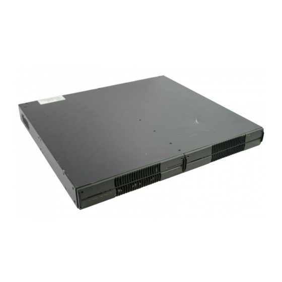
2 Product Overview 2.1 Introduction The RPS1000-A3 is an external power supply unit that uses AC inputs and provides eight lines of DC output, with a maximum output power of 2900 W. It can provide DC power supply simultaneously for multiple powered devices (such as switches and routers). -
Page 8: Front Panel
Note: The RPS1000-A3 supports hot backup of power supply. Namely, when the power supply system of the powered device operates normally, the RPS1000-A3 also provides part of the power supply to the device; when the power supply system of the powered device fails, the RPS1000-A3 becomes an independent power supply system. -
Page 9: Rear Panel
(4) DC 25-A outputs (5) DC 8-A outputs (6) Grounding screw (7) Fuses for the 8-A outputs Figure 2 Rear panel of the RPS1000-A3 Note: Each of the two AC inputs is for one power module; One reset button is provided for each of the two 25-A outputs. -
Page 10: Technical Specifications And Performance
2.4 Technical Specifications and Performance Table 2 Technical specifications of the RPS1000-A3 Item Specifications Dimensions (H × 44.45 × 440 × 393 mm (1.75 × 17.32 W × D) × 15.47 in.) Weight < 8 kg (< 17.64 lb.) Power module... - Page 11 Be sure to observe the relevant local laws and regulations when storing, using or disposing of this product. The RPS1000-A3 supports a variety of protection features, as shown in Table 3 on page 6. Table 3 Protection features of the RPS1000-A3...
- Page 12 Item Description When the output voltage exceeds –59.5 VDC, the power module comes into an over-voltage protection shutdown and Output generates an alarm. over-voltage To clear the alarm, remove the fault, protection and then pull out the power module and insert it again or turn off the AC input and turn it on again.
-
Page 13: Flatpack 1500 Power Module
Item Description At temperatures higher than 70℃ (158 ℉), the unit operates with reduced output power. At temperatures higher than 90℃ (194 High-temperat ℉), the unit comes into a ure protection high-temperature protection shutdown and generates an alarm. When the temperature comes down to 90℃... -
Page 14: Front Panel Of The Flatpack 1500
2.5.1 Front Panel of the Flatpack 1500 (1) Output current LEDs (2) Alarm LED (3) No-faults LED Figure 3 Front panel of the Flatpack 1500 2.5.2 LEDs Description Table 4 Flatpack 1500 LEDs description Mark on LEDs Status Meaning panel Output current indication: 0 to 30 A Output... -
Page 15: Output Specifications
Caution: When the alarm LED lights up, check for AC mains failure, output over-voltage condition, input over-voltage condition, input under-voltage condition, output over-current condition or high-temperature condition. For more information, refer to Table 3 on page 6. 2.6 Output Specifications 2.6.1 Output Power Distribution Table 5 Output power distribution Max. -
Page 16: Dc Output Cables
Caution: The RPS1000-A3 can provide power supply to multiple devices at the same time. Use one or two power modules depending on the power consumption of the powered devices. Make sure that: The system power consumption of each powered device does not exceed the maximum output power of the corresponding DC output;... -
Page 17: Installation
An A-direction plug connects with the DC power supply receptacle of a powered device, while a B-direction plug connects with a DC output of the RPS1000-A3. A JD5-A and a JD5 look alike except that a JD5 is a little bigger. - Page 18 Keep the RPS unit away from any heavy-duty radio transmitter, radar transmitter, and high-frequency devices working in high current. Take electromagnetic shielding measures if necessary. Make sure that the operating voltage of the power source matches the voltage required by the device. Interface cables must be routed indoors.
-
Page 19: Installing The Rps Unit
Note: Dust particle size ≥ 5µm Table 8 Limits on harmful gas concentration Limit (mg/m 0.006 0.05 0.01 3.2 Installing the RPS Unit The RPS1000-A3 can be installed either in a 19-inch standard rack or directly on a tabletop. -
Page 20: Installing The Rps Unit To A 19-Inch Rack
RPS unit to the rack; they cannot bear the weight of the RPS unit. When installing the RPS1000-A3 to a 19-inch rack, be sure to use a supporting tray or rear mounting ears to support the weight of the unit. - Page 21 Figure 4 Attach the front mounting ears and weight-bearing screws to the RPS unit Step 4: In accordance with the RPS unit installation position in the rack, fix the rear mounting rears to the rear square-holed brackets of the rack using M6 screws and cage nuts (user supplied), as shown in Figure 5 .
- Page 22 Figure 5 Install the rear mounting ears After pushing the RPS unit into the rack, make sure of the close contact between the upper edges of the rear mounting ears on the rack and the weight-bearing screws on the RPS unit, as shown in Figure 6 .
- Page 23 Figure 6 Install the RPS unit to the rack using front and rear mounting ears (1) Step 6: Fix the front mounting ears to the front square-holed brackets of the rack using M6 screws and cage nuts (user supplied), and make sure that the RPS unit is securely fixed with the front and rear mounting ears on the rack, as shown in Figure 7 .
- Page 24 Figure 7 Install the RPS unit to the rack using front and rear mounting ears (2) II. Installing the unit using front mounting ears and a supporting tray Step 1: Put on an ESD-preventive wrist strap and check the grounding and stableness of the rack.
- Page 25 Step 2: Fix the supporting tray supplied with the rack horizontally at the appropriate position of the rack. Step 3: Take out the supplied front ear screws and attach the front ears to the front end of the RPS unit using the screws, as shown in Figure 4 on page Figure 8 Install the RPS unit to the rack using front mounting ears and a supporting tray Step 4: Place the RPS unit horizontally on the...
-
Page 26: Installing The Rps Unit On A Tabletop
3.2.2 Installing the RPS Unit on a Tabletop If a 19-inch standard rack is not available, you can place the RPS unit directly on a clean, stable tabletop. Follow these steps to install the RPS unit on a tabletop: Step 1: Cautiously turn the RPS unit upside down. Then, use a piece of dry, soft cloth to remove any oil stain or dust from the dents on the bottom of the chassis. - Page 27 For pulling out the power module. With both handles released, you can use them to pull the power module part way out to detach it from the power module connector. Each handle has a locking mechanism that locks the handle in its slots. To release a handle, you need to insert a screwdriver (supplied with the RPS unit) into the hole at the corresponding upper corner of the front panel.
-
Page 28: Installing The Flatpack 1500
Caution: Never move the power module by its handles. When releasing the handles, do not use excessive force. When inserting the power module into the RPS chassis, make sure that the handles are unlocked. Upon inserting the power module into the chassis, push the handles into their slots to secure the power module in place. - Page 29 Step 2: With both hands holding the handles, gently pull the power module part way out so that it is detached from the connector, as shown in Figure 10 . Step 3: With one hand supporting the bottom and the other hand holding the power module, gently pull it out of the chassis.
-
Page 30: Connecting The Rps Unit To The Powered Devices
3.4 Connecting the RPS Unit to the Powered Devices 3.4.1 Connecting the cables Follow these steps to connect the RPS unit to a powered device: Step 1: Check that the power source to the RPS unit is disconnected and the powered device is powered off. -
Page 31: Commissioning The Rps Unit
Caution: Check that the AC input cable and the DC output cable are firmly connected to eliminate poor or loose contact. 3.4.2 Commissioning the RPS Unit Before powering on the RPS unit, check the AC input with a multimeter set to the resistance measurement function to eliminate any short circuit. - Page 32 Step 3: Remove the blown fuse and insert a spare fuse into the fuse cover. Verify that the fuse is in good contact with the spring at the bottom of the fuse cover. Step 4: Insert the new fuse together with the fuse cover into the fuse receptacle on the chassis, press down the fuse cover appropriately with a flat-blade screwdriver, and turn the fuse cover approximately...
Need help?
Do you have a question about the RPS1000-A3 and is the answer not in the manual?
Questions and answers