
Related Manuals for H3C RPS800-A


Summary of Contents for H3C RPS800-A
- Page 1 H3C RPS800-A User Manual Hangzhou H3C Technologies Co., Ltd. http://www.h3c.com Document version:APW100-20110420...
- Page 2 Copyright © 2011, Hangzhou H3C Technologies Co., Ltd. and its licensors All rights reserved No part of this manual may be reproduced or transmitted in any form or by any means without prior written consent of Hangzhou H3C Technologies Co., Ltd. Trademarks H3C,...
-
Page 3: Obtaining Documentation
The storage, use, and disposal of this product must meet the applicable national laws and regulations. Obtaining documentation You can access the most up-to-date H3C product documentation on the World Wide Web at http://www.h3c.com. Click the links on the top navigation bar to obtain different categories of product documentation: [Technical Support &... -
Page 4: Table Of Contents
Contents Product overview······················································································1 Introduction ·························································································1 Features ·······························································································2 Front panel ··························································································3 Rear panel···························································································3 LEDs ·····································································································4 Technical specifications ·····································································4 Installation·································································································6 Precautions··························································································6 Installing the RPS unit ·········································································8 Installing the RPS unit to a 19-inch rack ·····································8 Installing the RPS unit on a tabletop············································9 Connecting the grounding cable ···················································... -
Page 5: Product Overview
Product overview Introduction The RPS800-A is an external DC power supply that uses AC input and provides DC output for multiple switch and router models as a redundant backup power supply system. The RPS800-A supports cold backup of power supply, which means that the RPS800-A only switches to the RPS output state when it detects a power supply failure of the powered device. -
Page 6: Features
NOTE: For some models of powered devices, the control pin of the RPS800-A can be controlled through a special cable to support hot backup of power supply. When the power supply systems of the powered devices operate properly, the RPS unit also provides part of the power feed to the devices;... -
Page 7: Front Panel
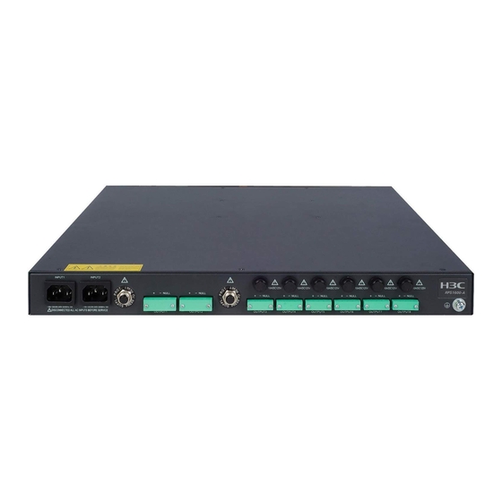
Front panel Figure 1 Front panel of the RPS800-A (1) AC Input LED (PWR) (2) DC output LED (OUT) Rear panel Figure 2 Rear panel of the RPS800-A (1) Grounding screw (2) AC input (3) DC output... -
Page 8: Leds
RPS. NOTE: The OUT LED lights up only when the RPS800-A switches to the RPS output state. When the RPS800-A works in the monitoring mode, its OUT LED stays off. Technical specifications... - Page 9 Item Specifications Weight < 3.8 kg (<8.38 lb) Input 100 to 240 VAC, 50/60 Hz –54 V/12 A • Available outputs +12 V/17.25 A • +12 V output 210 W only Maximu –54 V output 650 W m power only consump 210 W for +12 V output •...
-
Page 10: Installation
Installation Precautions To avoid any device impairment or bodily injury because of improper use, follow the precautions listed below: Do not place the RPS unit on an unstable case or tabletop, and • ensure that the rack and the workbench are firm enough to support the RPS unit and its accessories. - Page 11 from the outside of the building, you may add a dedicated lightening arrester at the input end of the cable. To enhance lightening protection, you may need to add a power • lightening arrester at the input end. Wear an ESD-preventive wrist strap when installing the RPS unit, •...
-
Page 12: Installing The Rps Unit
0.05 0.01 Installing the RPS unit The RPS800-A can be installed either in a 19-inch standard rack or directly on a tabletop. Installing the RPS unit to a 19-inch rack Follow these steps to install the RPS unit to a 19-inch rack:... -
Page 13: Installing The Rps Unit On A Tabletop
Step3 Place the RPS unit horizontally to an appropriate position in the rack, and then fix the mounting brackets to the front square-holed brackets of the rack with M6 screws and cage nuts, as shown in Figure Figure 4 Install the RPS unit to a 19-inch rack (II) Installing the RPS unit on a tabletop If a 19-inch standard rack is not available, you can place the RPS unit directly on a clean, stable tabletop. -
Page 14: Connecting The Grounding Cable
Step3 Turn over the RPS unit and place it on the tabletop. Verify the stableness and good grounding of the table. Connecting the grounding cable WARNING! Correctly connecting the grounding cable is crucial to lightning protection and EMI protection. Follow these steps to attach the OT terminal of the grounding cable to the grounding hole of the RPS unit: Step1 Remove the grounding screw from the rear panel of the RPS... - Page 15 Figure 5 Connect the grounding cable to the grounding hole of the RPS unit (1) Rear panel of the RPS unit (2) Grounding screw (3) OT terminal (4) Grounding cable (5) Grounding hole Follow these steps to attach the other end of the grounding cable to the grounding strip: Step1 Peel 5 mm (0.20 in) of insulation sheath by using a wire stripper,...
-
Page 16: Connecting The Rps Unit To The Powered Device
(4) Hex nut Connecting the RPS unit to the powered device The RPS800-A can be used as a redundant backup power supply unit for multiple switch and router models. The following describes how to connect the RPS unit to a switch. - Page 17 (5) Switch redundant power supply input (6) Switch rear panel (7) Switch AC input NOTE: The OUT LED lights up only when the RPS800-A switches to the RPS output state. When the RPS800-A works in the monitoring mode, its OUT LED stays off.
Need help?
Do you have a question about the RPS800-A and is the answer not in the manual?
Questions and answers