Advertisement
Advertisement
Table of Contents

Subscribe to Our Youtube Channel
Related Manuals for H3C DG-240-55


Summary of Contents for H3C DG-240-55
- Page 1 H3C DG-240-55 Industrial Power Supply Installation Quick Start New H3C Technologies Co., Ltd. http://www.h3c.com Document version: 5W100-20191025...
- Page 2 The information in this document is subject to change without notice. All contents in this document, including statements, information, and recommendations, are believed to be accurate, but they are presented without warranty of any kind, express or implied. H3C shall not be liable for technical or editorial errors or omissions contained herein.
- Page 3 Preface This document provides a quick start guide for installing the H3C DG-240-55 industrial power supply. It also covers the power supply views, technical specifications, and installation environment and guidelines. This preface includes the following topics about the documentation: •...
- Page 4 Convention Description Multi-level menus are separated by angle brackets. For example, File > Create > > Folder. Symbols Convention Description An alert that calls attention to important information that if not understood or followed WARNING! can result in personal injury. An alert that calls attention to important information that if not understood or followed CAUTION: can result in data loss, data corruption, or damage to hardware or software.
- Page 5 It is normal that the port numbers, sample output, screenshots, and other information in the examples differ from what you have on your device. Documentation feedback You can e-mail your comments about product documentation to info@h3c.com. We appreciate your comments.
-
Page 6: Table Of Contents
Contents 1 Preparing for installation ······························································· 1-1 Installation environment ············································································································ 1-1 Installation guidelines··············································································································· 1-1 2 Installing the power supply ···························································· 2-1 Mounting the power supply on a DIN rail ······················································································ 2-1 Removing the power supply from a DIN rail ·················································································· 2-1 3 Connecting power cords ·······························································... -
Page 7: Preparing For Installation
Preparing for installation H3C DG-240-55 industrial power supply is an AC-input and DC-output power supply designed for industrial Ethernet switches. It can be installed only on a TS-35/7.5 or TS-35/15 DIN rail. Installation environment Make sure you install the power supply in a favorable environment. - Page 8 • Ground the power supply reliably to ensure safety and reduce interference. • To avoid electric shock, do not remove the power supply housing. If the power supply is faulty, do not repair it yourself. Contact the technical support. • Make sure the operating voltage is correct and stable and does not exceed the nominal specifications to ensure the availability of the power supply.
-
Page 9: Installing The Power Supply
Installing the power supply Mounting the power supply on a DIN rail CAUTION: • Use a TS-35/7.5 or TS-35/15 DIN rail that complies with the EN 60715 or EN 50022 standard for mounting the power supply. • When calculating the total installation depth of the power supply, you must include the thickness of the DIN rail. - Page 10 Figure2-2 Removing the power supply from a DIN rail...
-
Page 11: Connecting Power Cords
Connecting power cords The power supply has power input and output terminals, used for connecting AC and DC power cords, respectively. The power cord wiring color codes vary by country and region. The wire colors in Figure3-1 are for illustration only. Figure3-1 Connecting power wires to the power supply Connecting an AC input power cord WARNING! -
Page 12: Connecting A Dc Output Power Cord
Connecting a DC output power cord Connect the DC output power wires to the wiring terminals at the top of the power supply, with the positive wire (red in Figure3-1) to a positive terminal (+V) and negative wire (black wire in Figure3-1) to a negative terminal (-V). -
Page 13: Appendix A Views And Technical Specifications
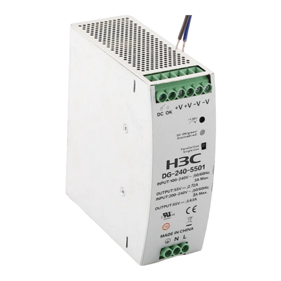
Appendix A Views and technical specifications Views Figure4-1 H3C DG-240-55 industrial power supply view Mark Description When the output voltage increases to 40±5 VDC, the relay DC (relay pin 1) closes the contact. When the output voltage decreases to 35±5 VDC, the relay OK (relay pin 2) opens the contact. -
Page 14: Technical Specifications
Mark Description A switch that controls parallel use or independent use of the Parallel Use/Single Use power supply. AC input live wire connection. AC input neutral wire connection. AC input PE wire connection. IMPORTANT: • The DC-OK relay detects the output voltage of the power supply. The maximum load that the DC-OK contact can bear is 30 VDC/1 A, 60 VDC/0.3 A, or 30 VAC/0.3 A. -
Page 15: Appendix B Protection Mechanism
Appendix B Protection mechanism The power supply has a protection mechanism against overcurrent, overvoltage, short circuit, and overtemperature conditions. Table5-1 Power supply protection mechanism Protection feature Protection mode Recovery Automatically recovers after the issues Overcurrent Does not provide power. The LED is are resolved. -
Page 16: Appendix D Leds
Appendix D LEDs The power supply provides a LED to indicate the power output state. Table6-1 LED description LED status Description Steady green The output voltage increases to 37.5±5 VDC. • The power supply has entered undervoltage protection mode. • The power supply has entered overcurrent protection mode.
Need help?
Do you have a question about the DG-240-55 and is the answer not in the manual?
Questions and answers