Table of Contents
Advertisement
Quick Links
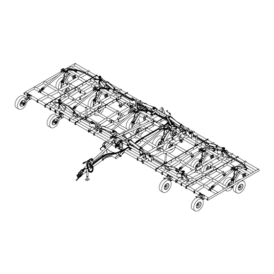
KONGSKILDE 8200 DF
Field Cultivator - Assembly/Parts
Models
768236901 8236 Field Cultivator (36.5')
768238901 8238 Field Cultivator (38.5')
768240901 8240 Field Cultivator (40.5')
768242901 8242 Field Cultivator (42.5')
768244901 8244 Field Cultivator (44.5')
768246901 8246 Field Cultivator (46.5')
768248901 8248 Field Cultivator (48.5')
*Model may not be exactly as shown.
Kongskilde reserves the right to make changes to product designs and
specifications without notice or obligation to rework.
See your local Kongskilde representative for current product specific-
ations and options.
760000229 - Revision 7
Serial No. 411391 - current
Advertisement
Table of Contents

Related Manuals for Kongskilde 8200 DF Series


Summary of Contents for Kongskilde 8200 DF Series
- Page 1 Field Cultivator - Assembly/Parts Models *Model may not be exactly as shown. Kongskilde reserves the right to make changes to product designs and 768236901 8236 Field Cultivator (36.5') specifications without notice or obligation to rework. See your local Kongskilde representative for current product specific- 768238901 8238 Field Cultivator (38.5')
-
Page 2: Table Of Contents
Table of Contents Introduction: ............................3 Center Frame Assembly ........................4 Center Rockshaft Assembly .........................6 Center Rockshaft Parts .........................8 Fold Cylinder Mount Assembly ......................10 Center Lift Cylinders & Linkages Assembly ..................12 Single Point Assembly ........................14 Light Stands & Safety Locks Assembly ....................16 Hitch &... -
Page 3: Introduction
Introduction: Please take the time to carefully read all the instruction booklets provided with your new Kongskilde product. Once you are finished reading do not throw these guides out. Keep them for later review. These instruction booklets have been developed to assist you in assembling, adjusting and maintain- ing your new Kongskilde Product. -
Page 4: Center Frame Assembly
Center Frame Assembly Instructions: -Hardware included in bag 760033040 -Connect center frames as shown, using parts listed on next page. -Place center frames on steel shop stands during assembly until lift hydraulics are installed and working. � � � � �... - Page 5 Parts list / 8200 DF Center Frame Assembly. Date: August 2014 Fig. Part no. Description 760032000 Center Mainframe Wdmt, LH 760032001 Center Mainframe Wdmt, RH 760032063 Leveling Pivot Linkage Mount 600356107 Bolt, 5/8" X 3" GR. 5 600356023 Bolt, 5/8" X 1 3/4" GR. 5 600366031 Nut, Toplock 5/8"...
-
Page 6: Center Rockshaft Assembly
Center Rockshaft Assembly Instructions: -Hardware included in bag 760033040 -Insert wear sleeves into rockshaft blocks before assembling rockshaft. -Assemble rockshaft, spindles and wheels to center frame as shown, using parts listed on next page. -Spindles and wheels can be installed to rockshaft assembly before or after rockshaft is attached to the frame -IMPORTANT: Install wheels to the spindles so the wheel rims are offset toward the wheel arms (Narrow setting). - Page 7 Parts list / 8200 DF Center Rockshaft Assembly. Date: August 2014 Fig. Part no. Description 760033003 Center Rockshaft Assembly 760031189 Center Rockshaft Block 7600355102 Bolt, 3/4" X 9-1/2" GR. 8 600366024 Nut, Toplock 3/4" 7600473119 8 X 8 Hub (G60-8) & Spindle Assembly 600355052 Bolt, 5/8"...
-
Page 8: Center Rockshaft Parts
Center Rockshaft Parts � �� �� �� �� �� �� �� � �� �� � � � � �� � �� � � �� �� �� ��... - Page 9 Parts list / 8200 DF Center Rockshaft Parts. Date: April 2015 Fig. Part no. Description 760032008 Center Rockshaft Wdmt 760032010 Center Tandem Wdmt 7600473116 6000# Spindle (2-3/4" x 18") w/Hole 7600473117 2-3/4" x 18" Spindle Assembly (Includes Items 3, 10, 11, 22) 763011289 8-Bolt Hub 60-8 (Includes Items 4, 7, 8, 13, 14) 763012379...
-
Page 10: Fold Cylinder Mount Assembly
Fold Cylinder Mount Assembly Instructions: -Hardware included in bag 760033040 -Attach fold cylinder mounts and cross brace as shown, using hardware on next page. � � � � � � � � � � � �... - Page 11 Parts list / 8200 DF Fold Cylinder Mount Assembly. Date: August 2014 Fig. Part no. Description 760032049 Rear Fold Cylinder Base Mount Wdmt 760032051 Center Frame Cross Brace Wdmt 760032050 Front Fold Cylinder Base Mount Wdmt 600355028 Bolt, 5/8" X 2" GR. 8 600381052 Flat Washer, 5/8"...
-
Page 12: Center Lift Cylinders & Linkages Assembly
Center Lift Cylinders & Linkages Assembly Instructions: -Hardware included in bag 760033041 -Attach lift cylinders and linkages as shown, using parts listed on next page. -On base end of cylinders, use pins which come with cylinders - pins shown are for repair only -Install leveling linkage as shown in image "A". - Page 13 Parts list / 8200 DF Center Lift Cylinders & Linkages Assembly. Date: May 2015 Fig. Part no. Description 7600474662 Cylinder 4 1/4” X 8” Welded Rephase - Monarch (8242, 8244, 8246, 8248) 7600474663 Cylinder 4" X 8" Welded Rephase - Monarch (8236, 8238, 8240) 760032057 Cylinder Linkage Wdmt 760032056...
-
Page 14: Single Point Assembly
Single Point Assembly Instructions: -Hardware included in bag 760033016 -Assemble upright bracket and valve to frame as shown, using hardware listed on next page. Bracket should be placed 8" from center frame rail. -Assemble striker bolt and spring to outer tube wdmt. Insert inner tube through outer tube and connect together with crank. - Page 15 Parts list / 8200 DF Single Point Assembly. Date: August 2014 Fig. Part no. Description 760032021 Single Point Upright Wdmt 76101322 U-Bolt, 3/8”-16 X 4” X 5” 600382051 Lockwasher, 3/8" 600365008 Nut, 3/8" 7600470491 Single Point Valve 600356148 Bolt, 5/16" X 2-1/2" GR. 5 600382050 Lockwasher, 5/16"...
-
Page 16: Light Stands & Safety Locks Assembly
Light Stands & Safety Locks Assembly Instructions: -Hardware included in bags 760033041 & 760033045 -Attach light stands and safety locks to center frame. -IMPORTANT: Light tubes should be mounted on stands as far outwards as possible on all double fold models except the 8238. The 8238 requires the light tubes to be mounted at the narrowest position. - Page 17 Parts list / 8200 DF Light Stands & Safety Locks Assembly. Date: August 2014 Fig. Part no. Description 760032024 Light Stand Wdmt 7600356163 Bolt, 3/8" X 2-3/4" GR. 5 600366028 Nut, Toplock 3/8" 760032025 Light Tube Wdmt 7600373128 U-Bolt, 3/8" X 2" X 3" 600382051 Lockwasher, 3/8"...
-
Page 18: Hitch & Turnbuckle Assembly
Hitch & Turnbuckle Assembly Instructions: -Hardware included in bags 760033040, 760033041, 760033045 & 760033016 (The hitch and components can be installed before or after the wing frames have been assembled to the center frame.) -Attach hitch, turnbuckle and components to center frame as shown, using hardware listed on next page. - Page 19 Parts list / 8200 DF Hitch & Turnbuckle Assembly. Date: May 2015 Fig. Part no. Description 760032015 Hitch Wdmt 760031082 Hitch Pivot Pin 7600356163 Bolt, 3/8" X 2-3/4" GR. 5 600366028 Nut, Toplock 3/8" 760033027 Turnbuckle Assembly (Includes Items 22-25) 7600355110 Bolt, 1"...
-
Page 20: Intermediate Wing Frame Assembly
Intermediate Wing Frame Assembly Instructions: -Hardware included in bags 760033020 & 760033043 -Bolt together wing frames as shown, using hardware listed on next page, and then attach to center frame. Use steel shop stands to support the wings until lift and fold hydraulics are installed and working. - Page 21 Parts list / 8200 DF Intermediate Wing Frame Assembly. Date: August 2014 Fig. Part no. Description 760032041 4.5' Innner Wing Frame Wdmt, LH, DF (Models 8248, 8246) 760032073 3.5' Innner Wing Frame Wdmt, LH, DF (Models 8244, 8242, 8240) 760032071 2.5' Innner Wing Frame Wdmt, LH, DF (Model 8238) 760032075 7’...
-
Page 22: Intermediate Fold Cylinder Assembly
Intermediate Fold Cylinder Assembly Instructions: -Hardware included in bag 760033043 -Attach fold cylinders to center and wing frames as shown, using parts listed on next page. -On base end of cylinders, use pins which comes with cylinders - pins shown are for repair only. �... - Page 23 Parts list / 8200 DF Intermediate Fold Cylinder Assembly. Date: August 2014 Fig. Part no. Description 7600474667 Cylinder 4 1/2” X 30” Welded - Monarch (Models 8248, 8246, 8244, 8242) 7600474666 Cylinder 4" X 30" Welded - Monarch (Models 8240, 8238, 8236) 600383136 Pin 1"...
-
Page 24: Wing Rockshaft Assembly
Wing Rockshaft Assembly Instructions: -Hardware included in bag 760033042 -Assemble rockshaft, spindles and wheels to intermediate wing frame as shown, using parts listed on next page. -Spindles and wheels can be installed to rockshaft assembly before or after rockshaft is attached to the frame -IMPORTANT: Install wheels to the spindles so the wheel rims are offset toward the wheel arms (Narrow setting). - Page 25 Parts list / 8200 DF Wing Rockshaft Assembly. Date: August 2014 Fig. Part no. Description 760033004 Wing Rockshaft Assembly LH 760033005 Wing Rockshaft Assembly RH (not shown) 760031218 Wing Rockshaft Block 760031083 Wing Rockshaft Block (Old - used w/o sleeves) 600355026 Bolt, 3/4"...
-
Page 26: Wing Rockshaft Parts
Wing Rockshaft Parts � �� �� �� �� �� �� �� �� � � � � �� �� � � � �� �� � �� �� ��... - Page 27 Parts list / 8200 DF Wing Rockshaft Parts. Date: April 2015 Fig. Part no. Description 760032009 Wing Rockshaft Wdmt 760032011 Wing Tandem Wdmt 763012199 Spindle 2" O.D. x 15" w/Hole 763012198 Spindle 2" O.D. x 15" w/Hole Complete (Includes Items 3, 10, 11, 22) 763011269 6 Bolt Hub - 6"...
-
Page 28: Wing Lift Cylinder & Linkage Assembly
Wing Lift Cylinder & Linkage Assembly Instructions: -Hardware included in bags 760033042, 760033043, 760033044 -Attach lift cylinder and linkage as shown, using parts listed on next page. -On base end of cylinders, use pins which comes with cylinders - pins shown are for repair only. -Adjust eyebolt to initial setting of about 4 3/8"... - Page 29 Parts list / 8200 DF Wing Lift Cylinder & Linkage Assembly. Date: August 2014 Fig. Part no. Description Intermediate Wing 7600474663 Cylinder 4” X 8” Welded Rephase - Monarch (Models 8248, 8246, 8244, 8242) 7600474664 Cylinder 3 3/4" X 8" Welded Rephase - Monarch (Models 8240, 8238, 8236) Outer Wing 7600474664 Cylinder 3 3/4"...
-
Page 30: Outer Wing Assembly
Outer Wing Assembly Instructions: -Hardware included in bags 760033020, 760033044 -Bolt together wing frames as shown, using hardware listed on next page (8248 is only model with two-piece outer wing) and then attach to center frame. Use steel shop stands to support the wings until lift and fold hydraulics are installed and working. - Page 31 Parts list / 8200 DF Outer Wing Assembly. Date: August 2014 Fig. Part no. Description 760032045 2.5' Outer Pivot Wing Frame Wdmt, LH, DF (Models 8248) 760032081 7' Outer Wing Frame Wdmt, LH, DF (Models 8246, 8244) 760032079 6' Outer Wing Frame Wdmt, LH, DF (Model 8242) 760032077 5’...
-
Page 32: Outer Fold Cylinder Assembly
Outer Fold Cylinder Assembly Instructions: -Hardware included in bag 760033044 -Attach fold cylinders to intermediate and outer wing frames as shown, using parts listed on next page. -On base end of cylinders, use pins which comes with cylinders - pins shown are for repair only. - Page 33 Parts list / 8200 DF Outer Fold Cylinder Assembly. Date: August 2014 Fig. Part no. Description 7600474676 Cylinder 4” X 20” Welded - Monarch (Model 8248, 8246, 8244, 8242) 7600474677 Cylinder 3 1/2" X 20" Welded - Monarch (Models 8240, 8238, 8236) 760032087 Float Linkage Wdmt (Models 8248, 8246, 8244, 8242) 760032089...
-
Page 34: Outer Wing Rockshafts And Linkages
Outer Wing Rockshafts and Linkages Instructions: -Install wing rockshafts and linkages to outer wings in the same manner as the intermediate wings. See pages 24 - 29. Wing Fold Stands Instructions: -Hardware included in bag 760033045 -Attach wing stands to intermediate frame using hardware listed on next page. Mount wing stand so they are leaning outwards. - Page 35 Parts list / 8200 DF Wing Fold Stands Assembly. Date: August 2014 Fig. Part no. Description 760032052 Wing Stand Wdmt, Short (Models 8248, 8246, 8244, 8242) 760032088 Wing Stand Wdmt, Tall (Models 8240, 8238, 8236) 7600373131 U-Bolt, 1/2” X 4” X 5.25” 600382053 Lockwasher, 1/2"...
-
Page 36: Vibrotine Assembly Option
Tine Assembly Instructions: -Install tine/coil assemblies onto cultivator. -Use tine layouts in Tine & Harrow Layout Manual 760000231 for proper placement. 1. Place coil clamp and bolt onto frame 2. Insert tine/coil assembly through clamp and bolt to frame. -Tighten bolt so that front of clamp bends down about 10°. See image on next page. �... - Page 37 Parts list / 8200 DF Tine Assembly. Date: March 2014 Fig. Part no. Description 101003154 16.3mm Coil 101003159 13.3mm Coil 101000837 Stem, 50mm x 10mm 760031123 16.3mm Coil Clamp 760031122 13.3mm Coil Clamp 6100323128 M12 x 48mm Share Bolt with Hex Nut 600355030 Bolt, 5/8"...
-
Page 38: C-Shank Assembly Option
C-Shank Assembly (Option) Instructions: -Use 6" tine layouts in Tine & Harrow Layout Manual 760000231 for proper placement of shanks. 1. Attach quick change bracket to c-shank assembly. 2. Detach spring from top bolt and install c-shank assembly on implement with u-bolt. 3. - Page 39 Parts list / 8200 C-Shank Assembly. Date: March 2015 Fig. Part no. Description 7601000556 Pivot Bracket Wdmt 7601000557 Tower Wdmt 7601000550 Inner Pivot Bushing Items 1-21 included in 760034005 7600383218 2-7/8" Connex Bushing C-Shank Assembly 601000501 C-Shank Stem 601000511 Spring Insert - Top 601000512 Spring Insert - Bottom 601000510...
-
Page 40: Gauge Wheel Assembly
Gauge Wheel Assembly Instructions: -Hardware included in bag 760033057 -After tines have been installed, assemble gauge wheels to outer front corners of intermediate and outer wing frames as shown, using the parts listed on next page. -Location will vary depending on tine spacing (gauge wheel not to extend beyond frame edge). -Repeat for opposite side. - Page 41 Parts list / 8200 DF Gauge Wheel Assembly. Date: Nov. 2014 Fig. Part no. Description 760032040 Gauge Wheel Bracket Mount 600373058 U-bolt, 5/8” X 4” X 5 1/2” 600381052 Flat Washer, 5/8" - SAE 600366031 Nut, Toplock 5/8" 760033061 Gauge Wheel Arm Assemlby (G35-6 Hub & single piece tab) 601231421 Gauge Wheel Arm Assembly (Old style with two tabs) 7600383215...
-
Page 42: Gauge Wheel Parts
Gauge Wheel Assembly Parts � �� � � � � � � � � �� �� �� Old Style Arm... - Page 43 Parts list / 8200 DF Gauge Wheel Assembly Parts. Date: April 2015 Fig. Part no. Description 760032095 Gauge Wheel Arm Weldment (G35-6 & single piece tab) 763011269 6 Bolt Hub - 6" Bolt Circle G35-6 (Includes Items 3, 4, 9, 10) 763011609 G35-6 Hub Assembly Complete (Includes Items 2-10) 76301135...
-
Page 44: Rear Jack Assembly
Rear Jack Assembly Instructions: -Install rear jack bracket onto rear bar of center mainframe with hardware provided. It is recom- mended to located bracket as near to the center of the cultivator as possible for better stability. � � � �... - Page 45 Parts list / 8200 DF Rear Jack Assembly. Date: March 2014 Fig. Part no. Description 760032058 Rear Jack Bracket 600356134 Bolt, 1/2" X 5-1/2" GR.5 600382053 Lockwahser, 1/2" 600365009 Nut, 1/2" 601231223 Jack TWL 190 DL-B...
-
Page 46: Hydraulic Tree Assembly
Hydraulic Tree Assembly Instructions: -Hardware included in bag 760033045. Fittings included in hydraulic kits. -Attach hydraulic hose tree to fold cylinder base weldment using hardware listed on next page. -Locate tree directly above the inner frame rail on the left mainframe. -It is recommended to install bulkhead fittings (included in hydraulic kit) one at a time from top down while routing hydraulic hoses. - Page 47 Parts list / 8200 DF Hydraulic Tree Assembly. Date: August 2014 Fig. Part no. Description 760032020 Fold Cylinder Base Mount Wdmt 760031115 Hyd Hose Tree 7600373129 U-Bolt, 3/8" x 3" x 2-3/4" 600382051 Lock Washer, 3/8" 600365008 Standard Nut, 3/8" 7600470474 #6 MJIC Bulkhead Tee 7600470475...
-
Page 48: Lift Hydraulics
Lift Hydraulics Instructions: -Hardware included in bag 760033045 & 760033016 -Connect hydraulic fittings and hoses as shown in this schematic. Refer to Appendix A for de- tailed routing information. -Secure hoses with hold downs provided. - Page 49 Parts list / 8200 DF Lift Hydraulics. Date: April 2015 Fig. Part no. Description 7600470478 Hyd Hose - 3/8" x 1/2" MPT x #8 FJIC - 204" 76202277 Hyd Hose - 3/8" x 1/2" MPT x #8 FJIC - 336" 7600470479 Hyd Hose - 3/8"...
-
Page 50: Fold Hydraulics
Fold Hydraulics Instructions: -Hardware included in bag 760033045 & 760033016 -Connect hydraulic fittings and hoses as shown in this schematic. Refer to Appendix A for de- tailed routing information. -Secure hoses with hold downs provided. - Page 51 Parts list / 8200 DF Fold Hydraulics. Date: April 2015 Fig. Part no. Description 7600470494 Hyd Hose - 1/4" x 1/2" MPT x #6 FJIC - 208" 7600470495 Hyd Hose - 1/4" x #6 FJIC x #6 FJIC - 128" 76202117 Hyd Hose - 1/4"...
-
Page 52: Cylinder Parts
Cylinder Parts Lift Cylinder Fold Cylinder... - Page 53 Parts list / 8200 DF Cylinder Parts. Date: March 2013 Fig. Part no. Description 7600474662 Cylinder 4 1/4" X 8" Welded Rephase - Monarch 7600474680 Clevis, Monarch #493837 7600474681 Seal Repair Kit, Monarch #649233 7600474663 Cylinder 4" X 8" Welded Rephase - Monarch 7600474669 Clevis, Monarch #493830 7600474682...
-
Page 54: Light Kit Assembly
Light Kit Assembly Instructions: -Connect electrical wiring from light kit as shown in the schematic below. Refer to Appendix A for detailed routing information. -Secure wiring with cable ties. 2-Pin Connector 3-Pin Connector 4-Pin Connector 4-Pin Connector 3-Pin Connector 2-Pin Connector... - Page 55 Parts list / 8200 DF Light Kit Assembly. Date: May 2015 Fig. Part no. Description 760033006 8200 Series Light Kit 760031240 Harness, 30' Lead w/7-Pole Ag Plug 760031241 Harness, 11' - Y, LH 760031242 Harness, 15' - Y, RH 760031243 Tail Light, Red 760031244 Warning Light, Amber...
-
Page 56: Rear Hitch (Optional)
Rear Hitch Assembly (Optional) Instructions: -Hardware included in bag 760033026 -Remove the two rear bolts connecting the center frame halves. -Attach the rear hitch weldment to the cultivator center frame using u-bolts provided. -Loosely attach the support arm and spacers to cultivator where the two bolts were removed. Use the u-bolts provided to attach the support arm to the rear hitch and tighten up all hardware. - Page 57 Parts list / 8200 DF Rear Hitch Assembly. Date: August 2014 Fig. Part no. Description 760032053 Rear Hitch Weldment 760032054 Support Arm Weldment 760031153 Telescoping Drawbar 1" 760031162 Support Arm Spacer 600373058 U-bolt, 5/8" X 4 X 5-1/2" 600373056 U-bolt, 5/8" X 3 X 5-1/2" 600356116 Bolt, 5/8"...
-
Page 58: Rear Hitch Hydraulic Kit (Optional)
Rear Hitch Hydraulic Kit Assembly (Optional) INSTALLING REAR HITCH HYDRAULIC KIT- 760034003 -Requires Optional Rear Hitch 760034002 1. Attach coupler mount bracket (1) to rear hitch using 1/2”-13 x 1.25 cap screws (7) and 1/2”-13 lock nuts (8) 2. Install male couplers (4) to 3/8" x 432" hoses (2). 3. - Page 59 Parts list / 8200 DF Rear Hitch Hydraulic Kit. Date: April 2015 Fig. Part no. Description 760035192 Bracket, Coupler Mount 7600470510 Hose 3/8"-8MP-8MP-432" LG 7600470496 Coupler, 1/2" Female-8FP Push/Pull 600470110 Coupler, 1/2" Male-8FP 7600407054 Ring, Ext. Retaining-1.50" x .05" 7600470498 Clamp, Hose Holder 600356103 Bolt, 1/2"-13 x 1.25"...
-
Page 60: Rear Hitch Light Extension Kit (Optional)
Rear Hitch Light Kit Extension (Optional) INSTALLING REAR HITCH LIGHT KIT EXTENSION - 760034006 -Requires Optional Rear Hitch 760034002 1. Attach coupler mount bracket using 3/8” x 1” bolts (3) and toplock nuts (4). 2. Run extension wiring harness (2) through cut out in left arm of rear hitch and down inside arm. Note: If installing optional hydraulic kit, run hoses and harness at same time. - Page 61 Parts list / 8200 Rear Hitch Light Kit Extension. Date: March 2014 Fig. Part no. Description 760031213 Bracket, 7 Pole Socket Mount 760031214 Harness, 8' Extension w/ 7 Pole Socket 600356020 Bolt, 3/8" x 1" GR. 5 600366028 Nut, Toplock, 3/8" 600356106 Bolt, 5/16"...
-
Page 62: Decal Placement
Decal Placement Instructions: -Attach decals to clean surface as shown below ��������� � � � � � � � � � �� �� �� � �� ����������������������� ���������� � � ����������������������������� �� �� �������������� � ���������� � � ����������������������� ���������������������������� ����������������... - Page 63 Parts list / 8200 DF Decal Placement. Date: April 2015 Fig. Part no. Description 7600475260 Kongskilde 8200 Decal 600475237 Kongskilde Decal 7600475258 8200 Depth Gauge Decal 7600475259 8200 Depth Adjust Decal 600475039 Wing Safety Decal 600475176 Decal Wing Fold Lock...
-
Page 64: Assembly Completion
Assembly Completion After assembly is complete, charge the wheel lift cylinders with a tractor or hydraulic unit, fully extending and retracting the cylinders several times. Hold the hydraulic lever open at the end of the stroke to purge the air from the system. Fully extend the lift cylinders and install the transport safety locks onto the center lift cylinders. - Page 65 Appendix A Hydraulic Hose Routing Details Route hoses to single point Route hoses along hitch From To Rear Tractor Hydraulic Tree 3/8" Hoses on outside Route hoses along mainframe to hydraulic tree. Locate cross fittings behind front fold cylinder cross brace. 3/8"...
- Page 66 Appendix A Route hoses from intermediate lift Allow enough slack in hoses to cylinders to outer wing lift cylinders reach outer wing pivot Route hoses from front "cross" fittings and rear hydraulic tree to inner fold cylinders Route hoses from inner fold cylinders to outer fold cylinders...
- Page 67 Appendix A Safety Lighting Wire Routing Details Route light wiring from hitch to rear of machine following the hydraulic hoses. Route around fold cylinder mount and between rear fold stop plates Route wiring up light stands to lights as shown Rear View Left Side...
- Page 68 Appendix B Torque Chart...
- Page 69 Notes:________________________________________________________ ______________________________________________________________ ______________________________________________________________ ______________________________________________________________ ______________________________________________________________ ______________________________________________________________ ______________________________________________________________ ______________________________________________________________ ______________________________________________________________ ______________________________________________________________ ______________________________________________________________ ______________________________________________________________ ______________________________________________________________ ______________________________________________________________ ______________________________________________________________ ______________________________________________________________ ______________________________________________________________ ____________________________________________________________ _____________________________________________________________ _____________________________________________________________ _____________________________________________________________ _____________________________________________________________ _____________________________________________________________ _____________________________________________________________ _____________________________________________________________ _____________________________________________________________ _____________________________________________________________ _____________________________________________________________ _____________________________________________________________ _____________________________________________________________ _____________________________________________________________ _____________________________________________________________ _____________________________________________________________ _____________________________________________________________ _____________________________________________________________ _____________________________________________________________...
- Page 70 760000229 May 2015...
Need help?
Do you have a question about the 8200 DF Series and is the answer not in the manual?
Questions and answers