Sign In
Upload
Download
Table of Contents
Contents
Add to my manuals
Delete from my manuals
Share
URL of this page:
HTML Link:
Bookmark this page
Add
Manual will be automatically added to "My Manuals"
Print this page
×
Bookmark added
×
Added to my manuals
Manuals
Brands
BFT Manuals
Automatic Barriers
GIOTTO BT A 30 U
Installation and user manual
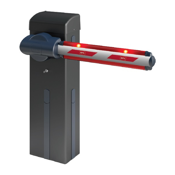
BFT GIOTTO BT A 30 U Installation And User Manual
Electromechanical control device for vehicular barriers a
Hide thumbs
1
2
3
4
5
6
7
8
9
10
11
12
13
14
15
16
17
18
19
20
21
22
23
24
25
Table Of Contents
26
page
of
26
Go
/
26
Contents
Table of Contents
Bookmarks
Advertisement
Table of Contents
1
General Safety
2
Installer Warnings
3
Quick Installation
4
Preliminary Adjustments
5
Expansion Board
6
Maintenance
7
Limit Switch Setting
8
Safety Devices
9
Serial Mode
Download this manual
ELECTROMECHANICAL CONTROL DEVICE FOR VEHICULAR BARRIERS A
Caution! Read "Warnings" inside carefully!
Table of
Contents
Previous
Page
Next
Page
1
2
3
4
5
Advertisement
Table of Contents
Need help?
Do you have a question about the GIOTTO BT A 30 U and is the answer not in the manual?
Ask a question
Questions and answers
Related Manuals for BFT GIOTTO BT A 30 U
Automatic Barriers BFT GIOTTO BT A 30S U Installation And User Manual
Electromechanical control device for vehicular barriers a (26 pages)
Automatic Barriers BFT GIOTTO BT A 60 U Installation And User Manual
Electromechanical control device for vehicular barriers a (26 pages)
Automatic Barriers BFT GIOTTO BT A 60S U Installation And User Manual
Electromechanical control device for vehicular barriers a (26 pages)
Automatic Barriers BFT ART90 BOOM PS GIOTTO ULTRA 36 Installation And User Manual
Articulated boom for giotto bt a ultra 36 (9 pages)
Automatic Barriers BFT ART90 BAR PS Installation And User Manual
Articulated boom (8 pages)
Automatic Barriers BFT GIOTTO 30 S BT Installation And User Manual
Electromechanical control device for vehicular barriers (21 pages)
Automatic Barriers BFT GIOTTO BT A ULTRA 36 Installation And User Manual
(31 pages)
Automatic Barriers BFT GIOTTO BT A ULTRA 36 Installation And User Manual
Electromechanical control device for vehicular barriers (64 pages)
Automatic Barriers BFT OMEGA ES GIOTTO ULTRA 36 Installation And User Manual
(8 pages)
Automatic Barriers BFT GIOTTO 30-60 S BT Installation And User Manual
(56 pages)
Automatic Barriers BFT GIOTTO ULTRA 36 XL Installation And User Manual
(31 pages)
Automatic Barriers BFT MAXIMA ULTRA 35 Instructions For Installation, Use And Maintenance Manual
(12 pages)
Automatic Barriers BFT MAXIMA ULTRA 36 Instructions For Installation, Use And Maintenance Manual
(21 pages)
Automatic Barriers BFT MAXIMA ULTRA 68 Installation And User Manual
(17 pages)
Automatic Barriers BFT MOOVI 30 Installation And User Manual
Electromechanical control device for vehicular barriers (40 pages)
Automatic Barriers BFT MAXIMA ULTRA 36 Quick Reference Manual
(20 pages)
This manual is also suitable for:
Giotto bt a 30s u
Giotto bt a 60 u
Giotto bt a 60s u
Table of Contents
Save PDF
Print
Rename the bookmark
Delete bookmark?
Delete from my manuals?
Login
Sign In
OR
Sign in with Facebook
Sign in with Google
Upload manual
Upload from disk
Upload from URL


Need help?
Do you have a question about the GIOTTO BT A 30 U and is the answer not in the manual?
Questions and answers