Advertisement
Table of Contents
- 1 Table of Contents
- 2 Control of the Conformity of the Electrical Line and the Compressed Air Network
- 3 The Message " Power Fault " Appears on the Display
- 4 Wire Cut on the Gun Command Cable
- 5 Issues Around the Thermal Sensor Inside the Gun
- 6 The Display of the Machine Is Blocked
- 7 Cooling Liquid Leaks
- 8 Diagnosis of the Power Functions of the Machine
- 9 Auxiliary Power Supply Issue on the Main Board
- 10 Messages in Foreign Languages
- Download this manual
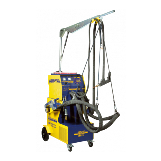
GYS
Welding machines - Battery chargers
GYSPOT 125L & 93R
Page 1
GYSPOT 125L & 93R Repair Procedure
CONTENTS
1) Control of the conformity of the electrical line and the compressed air network ...................................................2
2) The message « Power Fault » appears on the display .............................................................................................3
3) Wire cut on the gun command cable .......................................................................................................................3
4) Issues around the thermal sensor inside the gun .....................................................................................................4
5) The display of the machine is blocked ....................................................................................................................4
6) Cooling liquid leaks ................................................................................................................................................6
7) Diagnosis of the Power Functions of the machine ..................................................................................................6
8) Auxiliary power supply issue on the main board ....................................................................................................8
9) Messages in foreign languages................................................................................................................................9
Advertisement
Table of Contents

Related Manuals for GYS GYSPOT 125L


Summary of Contents for GYS GYSPOT 125L
-
Page 1: Table Of Contents
Welding machines – Battery chargers GYSPOT 125L & 93R Page 1 GYSPOT 125L & 93R Repair Procedure CONTENTS 1) Control of the conformity of the electrical line and the compressed air network ...........2 2) The message « Power Fault » appears on the display .....................3 3) Wire cut on the gun command cable ........................3... -
Page 2: Control Of The Conformity Of The Electrical Line And The Compressed Air Network
Welding machines – Battery chargers GYSPOT 125L & 93R Page 2 1) Control of the conformity of the electrical line and the compressed air network The electrical line must comply with the following requirements : Check the electrical line voltage : you must have 400V with a 32 A delayed circuit breaker, curve D (or fuse of aM type). -
Page 3: The Message " Power Fault " Appears On The Display
Welding machines – Battery chargers GYSPOT 125L & 93R Page 3 2) The message « Power Fault » appears on the display Check whether the electrical line complies to the requirements described in paragraph 1. Check whether the 3 phases are correctly connected to the machine. -
Page 4: Issues Around The Thermal Sensor Inside The Gun
Welding machines – Battery chargers GYSPOT 125L & 93R Page 4 Check the continuity of the wires going from the microswitch to the connector on the display board inside the machine. 4) Issues around the thermal sensor inside the gun The thermal sensor inside the monopoint gun provides information to the machine regarding the temperature inside the gun. - Page 5 The GYS reference of this button is 51186. If necessary, it can be provided if using abrasive paper does not solve the issue.
-
Page 6: Cooling Liquid Leaks
Welding machines – Battery chargers GYSPOT 125L & 93R Page 6 6) Cooling liquid leaks Cooling liquid leaks are sometimes observed at the extremity of the power cable, as shown on the photograph left. A standard collar, with screw, diameter... - Page 7 Welding machines – Battery chargers GYSPOT 125L & 93R Page 7 Switch ON the machine NOT OK Control the 3 phases Check the machine circuit at the input of the breaker, and connections inside diode bridge the plug. ( See instructions on next page )
-
Page 8: Auxiliary Power Supply Issue On The Main Board
Welding machines – Battery chargers GYSPOT 125L & 93R Page 8 Control of the 3 phases at the input of the diode bridge : Check, using a multimeter, that the 3 phases are present at the input of the diode bridge. Check between inputs 1 and 2, between inputs 2 and 3, and finally between inputs 1 and 3. -
Page 9: Messages In Foreign Languages
Welding machines – Battery chargers GYSPOT 125L & 93R Page 9 9) Messages in foreign languages FRENCH : SURCHAUFFE DES CABLES ENGLISH : OVERHEATING OF CABLES GERMAN : UBERHITZUNG VON KABEL SPANISH : RECALENTAMIENTO CABLES FRENCH : DEFAUT ALIMENTATION PUISSANCE... - Page 10 Welding machines – Battery Chargers GYSPOT 125L / 93R Page 1 GYSPOT 125L / 93R : Replacement of the power board and IGBT modules 1) Unplug the machine from the mains power supply. 2) Remove the top metallic cover of the machine.
- Page 11 Welding machines – Battery Chargers GYSPOT 125L / 93R Page 2 Unplug this connector Unplug this connector Unplug these 2 connectors from the board Remove terminals from the connector under the board. (be careful to plug every wire back correctly)
- Page 12 Welding machines – Battery Chargers GYSPOT 125L / 93R Page 3 5x Screws, for Flat end screw driver. Make sure you collect the washers also ! 4 Allen key head screws, on the IGBT modules.
- Page 13 Welding machines – Battery Chargers GYSPOT 125L / 93R Page 4 1 PHILIPS head screw, on Diode bridge. 1 bolt. Take these bars off and fix them on the other board.
- Page 14 Welding machines – Battery Chargers GYSPOT 125L / 93R Page 5 Unscrew the IGBT modules, and replace them. Make sure, when you put another board in the machine that there is space between each green resistor (a few mm in between).
- Page 15 Page 1 GYSPOT 93R and 125L : Test of the diode bridge The following procedure describes how to test the diode bridge on GYSPOT 125L machines. First of all, switch off the machine, and unplug from the mains power supply.
- Page 16 Welding machines – Battery chargers GYSPOT 93R and 125L Page 2 The photograph left, and the diagram below show how the diodes are connected inside the bridge. Using a multimeter in diode position, check that each and every diode is functional. Check that each diode conducts on one polarity, and blocks the current on the other polarity.
- Page 17 Welding machines – Battery chargers GYSPOT 125L Page 1 GYSPOT 125L : Procedure for the replacement of a power cable on an X-clamp This procedure describes how to change the power cable of an X-clamp. It applies both to GYSPOT 125L-X and 125L-Integral machines.
- Page 18 Welding machines – Battery chargers GYSPOT 125L Page 2 Then, remove the lateral screw to be able to take the cable off its housing. Pull the cable in order to remove it from its housing, as shown with the arrow.
- Page 19 Assembly of new sheath and new cable : In order to assemble the new sheath (GYS reference 11216), it is best to disconnect the remaining cable and pipes from inside the machine. (1) when both screws are removed, the remaining cable can be extracted from the machine side.
- Page 20 Welding machines – Battery chargers GYSPOT 125L Page 4 Disconnect the white pipe from the solenoid valve. Disconnect the connector on the display board. Then the old sheath can be removed. Connect the new cable to the clamp. Place the cables and clamp on a table, so that it lies flat : this is the best conditions to assemble the new sheath on both cables.
- Page 21 GYSPOT 125L : Replacement of gun command cable This procedure describes how to perform the replacement of the gun command cable on GYSPOT 125L machines. The idea is to cut the existing command cable on both ends, and assemble a new command cable on the outside of the sheath of the gun cable.
- Page 22 Welding machines – Battery chargers GYSPOT 125L Page 2 On the Gun side : Open the gun plastic casing. Remove the power cable and mandrel from their housing. Remove the command cable and switch. Cut the old command cable at the location shown on the photograph left.
- Page 23 Welding machines – Battery chargers GYSPOT 125L Page 3 On the machine side : The gun cable is located on the right side of the machine The command cable on this side comes with 3 wires connected on a connector.
Need help?
Do you have a question about the GYSPOT 125L and is the answer not in the manual?
Questions and answers