Table of Contents
Advertisement
Quick Links
Instructions
®
InvisiPac
Hot Melt Applicator
For dispensing hot melt adhesive. For professional use only.
Not approved for use in explosive atmospheres or hazardous locations.
See page 3 for model information, including working
pressures and approvals.
Important Safety Instructions
Read all warnings and instructions in this
manual and in all related manuals before
using the equipment. Save all
instructions.
GM100 Plug-Free
™
Conforms to ANSI/UL Std.
499 Certified to CAN/CSA
334627K
EN
4002346
st. C22.2 No 88
Advertisement
Table of Contents

Related Manuals for Graco InvisiPac GM100 Plug-Free

Summary of Contents for Graco InvisiPac GM100 Plug-Free
- Page 1 Instructions ® ™ InvisiPac GM100 Plug-Free 334627K Hot Melt Applicator For dispensing hot melt adhesive. For professional use only. Not approved for use in explosive atmospheres or hazardous locations. See page 3 for model information, including working pressures and approvals. Important Safety Instructions Read all warnings and instructions in this manual and in all related manuals before...
-
Page 2: Table Of Contents
Technical Specifications ....45 Graco Standard Warranty ....46... -
Page 3: Related Manuals
Related Manuals Related Manuals Manual Description 332072 InvisiPac Heated Hose Instructions - Parts 333347 InvisiPac HM25 Tank-Free Hot Melt Delivery System Models Low Profile - Quad All models use a 240 V heater. Part RTD Type Solenoid Valve Applicators with Ni 120 RTD types come with a 6-pin rectangular cordset (24X040 for slim, 24X761 for 25B033 Pt 100 (385) -
Page 4: Warnings
Warnings Warnings The following warnings are for the setup, use, grounding, maintenance, and repair of this equipment. The exclama- tion point symbol alerts you to a general warning and the hazard symbols refer to procedure-specific risks. When these symbols appear in the body of this manual or on warning labels, refer back to these Warnings. Product-specific hazard symbols and warnings not covered in this section may appear throughout the body of this manual where applicable. - Page 5 Warnings WARNING FIRE AND EXPLOSION HAZARD Flammable fumes, such as solvent and paint fumes, in work area can ignite or explode. Paint or solvent flowing through the equipment can cause static sparking. To help prevent fire and explosion: • Use equipment only in well-ventilated area. •...
-
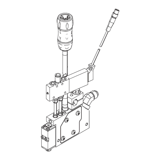
Page 6: Component Identification
Component Identification Component Identification Slim model shown on the left. Dual Low Profile model shown on the right. . 1: Hot Melt Applicator Component Identification Key: Module Mounting Clamp (1/2 in, diameter bar) Fluid Outlet Solenoid valve (24 VDC) Fluid Filter Air inlet (1/4 in. -
Page 7: Overview
Overview Overview Grounding The applicator uses the air-opened, air-closed mode of operation. It uses a five-way exhausting solenoid to control the piston inside the valve. Fluid is filtered through the manifold filter (C) before entering the valve The equipment must be grounded to reduce the risk fluid inlet port. -
Page 8: Installation
Installation Installation Mounting 2. Remove the existing clamp and replace the bottom part with the new clamp A. NOTICE 3. Before mounting to the rod, loosely thread screw C To prevent heat transferring into other components of into block A and thread screw D through block B into the packaging line, ensure that the insulator is the assembly. -
Page 9: Recommended Air Setup
Installation Recommended Air Setup Connect Triggering Device 1. Connect tubing from the air filter (Graco part no. All GM100 valves use a 24 VDC solenoid valve. If the 106148) to the air regulator. voltage to the solenoid exceeds 24 VDC, premature failure will occur. -
Page 10: Flush
Installation Flush Install Nozzle Use a 1/2 in. wrench to install the nozzle. See Kits and Accessories on page 37. NOTE: Do NOT cycle the module until the temperature setpoint has been achieved. Cycling the module below the temperature setpoint may cause premature seal leakage. -
Page 11: Operation
Operation Operation Pressure Relief Procedure Follow the Pressure Relief Procedure whenever you see this symbol. This equipment stays pressurized until pressure is manually relieved. To help prevent serious injury from pressurized fluid, such as skin injection and splashing fluid, follow the Pressure Relief Procedure when you stop spraying and before cleaning, checking, or servicing the equipment. -
Page 12: Maintenance
Clean hot melt from the exterior of the applicator. To establish a preventative maintenance cycle tailored to Weekly: your environment, Graco recommends inspecting filters Inspect the applicator, fluid lines, cordset, and solenoid every 4 weeks after installation and replacing when cable for wear or damage. -
Page 13: Troubleshooting
Troubleshooting Troubleshooting 1. Follow the Pressure Relief Procedure on page 11 before checking or repairing the applicator. 2. Check all possible problems and causes before disassembling the applicator. Problem Cause Solution No adhesive or incorrect amount of Plugged manifold filter Replace the manifold filter. - Page 14 Troubleshooting Problem Cause Solution Applicator will not heat Heater failure Check and replace the heater cartridge. See Replace Heater Cartridge on page 19. Loose cordset connection Check connection. RTD failure Check and replace the RTD. See Check RTD on page 18. Incorrect RTD for adhesive delivery Check the delivery system RTD system...
- Page 15 Troubleshooting Problem Cause Solution Speed has reduced on one module Low air pressure to solenoid valve Check the air supply. Low fluid pressure Check the adhesive delivery system. Low applicator temperature Check the heat operation. See the “Applicator will not heat” section on page 14.
-
Page 16: Check Module
Troubleshooting Check Module Check Nozzle and Module Check the module operation to verify if the module has Trigger the applicator without the nozzle to determine if failed and needs to be replaced. the nozzle of the module is clogged. 1. Disable the applicator assembly. See Before 1. -
Page 17: Check Heater
Troubleshooting Check Heater Table 1: 24W087, 24X039, 24X760, or 25E783 Pt 100 (385) RTD Cordset Check the continuity of the heater to verify proper Description resistance. If there is no continuity, the heater has failed Thermal Cutoff and needs to be replaced. Ground 1. -
Page 18: Check Rtd
Troubleshooting Check RTD Check Thermal Cutoff Check the continuity of the RTD to verify proper If working properly, the cutoff will trip at 500° F (260° C) resistance. If here is no continuity, the RTD has failed and rest at 420° F (216° C). If failure is suspected, allow and needs to be replaced. -
Page 19: Repair
Repair Repair Required Tools Replace Heater Cartridge NOTE: Depending on the model, the heater may be • Phillips screwdriver retained by a stainless steel plug pressed into the • Flat blade screwdriver applicator body. You must remove this plug before the •... -
Page 20: Replace Heater Plug
Repair Replace Cover Gasket NOTE: Do not apply thermal grease to the heater cartridge. NOTE: This is only required for 25B021 and 25B024 7. For 25B021 and 25B024 applicators only, inspect applicators. the cover gasket for damage and replace it if necessary. -
Page 21: Wiring Diagram
Repair d. Crimp the other thermal cutoff lead (29) to one g. Center the sleeves (30) over each taped splice. of the heater wires (3). 5. Gently press the wires into the manifold. Install the plate (18) and screws (15). e. -
Page 22: Replace Cordset
Repair Replace Cordset NOTE: Do not apply grease on the RTD or thermal cutoff. The replacement cordset (17) depends on the model you are using. 25B021 and 25B024 applicator cordsets 13. Insert the heater cartridges (3) in the manifold (1). have a black rubberized coating over the metal conduit. -
Page 23: Replace Solenoid Valve
Repair Replace Solenoid Valve Replace Module 1. Disable the applicator. See Before Beginning Repair on page 19. 2. Turn off the air supply to the solenoid valve. Material inside the applicator can be near the setpoint temperature. Wear protective clothing to avoid severe 3. -
Page 24: Replace Applicator
Repair Replace Applicator 5. Hold a rag over the manifold air ports and turn the air supply ON to clean the ports as shown in Figure 1. Disable the applicator. See Before Beginning Repair on page 19. 2. Loosen the mounting bar clamp and remove the applicator from the mounting bar. - Page 25 Repair Notes: 334627K...
-
Page 26: Parts
Parts Parts Slim (25B021, 25B024) Apply a thin coating of lubricant to seals. Apply lubricant to the first .05 in. of the thread of the bolts (22) before installing the module (2). Torque to 30 +/- in-lb (3.3 +/- 0.2 N•m). Torque to 15-20 in-lb (1.7-2.2 N•m). - Page 27 Parts Slim Parts List Part Description MANIFOLD, single 25B241 MODULE, ac, gm100 3 24X043 HEATER, rod 4† CONNECTOR, butt splice 5 16K931 TAG, warning 129647 SCREW, set, sh, cup m3 x 4 mm, sst 9 24X038 SOLENOID, quick disconnect 10 --- INSULATOR, slim CLAMP, top CLAMP, bottom...
-
Page 28: Dual (25B075, 25B301)
Parts Dual (25B075, 25B301) Apply a thin coating of lubricant to seals. Apply lubricant to the first .05 in. of the thread of the bolts (22) before installing the module (2). Torque to 30 +/- in-lb (3.3 +/- 0.2 N•m). Torque to 10-12 in-lb (1.1-1.3 N•m). - Page 29 Parts Dual Parts List Part Description MANIFOLD, dual, gm100, machined 25B241 MODULE, ac, gm100 3 24X242 HEATER, rod 4† CONNECTOR, butt splice 5 16K931 TAG, warning 17D782 PLATE, electrical, gm100, dual 128220 INSULATOR, electrical, dual 124736 SCREW, set, cup, m4 x 0.7 x 4 mm, sst 9...
-
Page 30: Quad (25B077, 25B303, Gsc079, Gsc080)
Parts Quad (25B077, 25B303, GSC079, GSC080) Type 1 Shown Apply a thin coating of lubricant to seals. Apply lubricant to the first .05 in. of the thread of the bolts (22) before installing the module (2). Torque to 30 +/- in-lb (3.3 +/- 0.2 N•m). Torque to 10-12 in-lb (1.1-1.3 N•m). - Page 31 Parts Quad Parts List Part Description MANIFOLD, quad, mini, machined 25B241 MODULE, ac, gm100 3 24X758 HEATER, 240 vac, 375w, 8 mm dia 4† CONNECTOR, butt splice 5 16K931 TAG, warning 17A618 COVER, electric, gm100, quad 128219 INSULATOR, electrical, quad 124736 SCREW, set, cup, m4 x 0.7 x 4 mm, sst 9...
-
Page 32: Low Profile Quad (25B033, 25B036)
Parts Low Profile Quad (25B033, 25B036) Apply a thin coating of lubricant to seals. Torque to 15-20 in-lb (1.7-2.2 N•m) Torque to 20-30 in-lb (2.2-3.3 N•m). Apply sealant to threads. The head of the plug needs to be flush with the housing Apply lubricant to the first .05 in. - Page 33 Parts Low Profile Quad Parts List Ref Part Description Ref Part Description MANIFOLD, quad, lp, mini, INSULATOR, electrical, back 128008 machined plate 25B241 MODULE, ac, gm100 24X456 CABLE, m8, 3-pin, 5.0 m HEATER, 240 vac, 375w, 8 mm 53 17F001 TAG, instruction 3...
-
Page 34: Low Profile Dual (25B027, 25B030)
Parts Low Profile Dual (25B027, 25B030) Torque to 10-12 in-lb (1.1-1.3 N•m). Apply a thin coating of lubricant to seals. Apply sealant to threads. The head of the plug Torque to 15-20 in-lb (1.7-2.2 N•m) needs to be flush with the housing Torque to 20-30 in-lb (2.2-3.3 N•m). - Page 35 Parts Low Profile Dual Parts List Ref Part Description --- Not available for individual sale. MANIFOLD, dual, lp, mini, Included in the Quad Mounting Clamp Kit. See Kits machined and Accessories on page 37. 25B241 MODULE, ac, gm100 † Included with all Heater, Cordset, and Overtemp 3...
-
Page 36: Solenoid Valve Kits
Solenoid Valve Kits Solenoid Valve Kits 24X038, 24 VDC Solenoid Valve . 25 Ref Part Description Qty. VALVE, solenoid, 5w, sr, 24 VDC 17A633 FITTING, 1/4 push-to-connect, 128478 FITTING, m6 push-to-connect, m7 (not shown) 24X044 KIT, solenoid tube with o-rings 295685 O-RING 106560... -
Page 37: Kits And Accessories
Kits and Accessories Kits and Accessories Module Replacement Insulator Gaskets Part Description 25E241 18A386 Slim Part Description Qty. 128220 Dual 128219 Quad, Quad 1.5 MODULE 127943 Dual LP 111119 SCREW, valve 128007 Quad LP (side) 24R835 O-RING, fluid (10 pack) 128008 Quad LP (back) 24T179... -
Page 38: Inlet Filter
Kits and Accessories Inlet Filter Mounting Clamp Kits Qty. 24X042 (Slim) 24P275 Single Part Description Qty. 24P802 3 Pack 17A496 INSULATOR, clamp, bar, housing Material Inlet Fittings 11a --- CLAMP, top 11b --- CLAMP, bottom Single Kit Description SCREW, valve 24P615 Straight 108050... - Page 39 Kits and Accessories 24X243 (Low Profile Dual) Nozzles (Single Orifice) Part Description Qty. Single 5 Pack Description 24P276 INSULATOR, clamp, bar, 24P636 24P794 0.008 straight housing 24P637 24P795 0.010 straight BLOCK, mating, low profile 24P638 24P796 0.012 straight 108050 WASHER, lock, spring 24P639 24P797 0.016 straight...
-
Page 40: Dimensions
Dimensions Dimensions Slim Dimensions 1.075 (27.305 mm) 2.735 (69.47 mm) 5.976 (151.79 mm) 3.774 (95.86 mm) 3.067 (77.90 mm) 2.557 (64.95 mm) .350 (8.89 mm) 2.250 .700 (57.15 mm) (17.78 mm) .749 (19.02 mm) 3.999 (101.57 mm) 5.082 (129.08 mm) . -
Page 41: Dual Dimensions
Dimensions Dual Dimensions 6.14 (155.96 mm) (20.07 mm) (19.05 mm) 3.29 (83.57 mm) 2.72 (69.09 mm) 2.01 (22.35 mm) (9.40 mm) (51.05 mm) 1.58 3.68 (40.13 mm) (93.47 mm) 4.22 (107.19 mm) 4.49 (114.05 mm) . 27: Models 25B075 and 25B301 334627K... -
Page 42: Quad Dimensions
Dimensions Quad Dimensions 6.14 (155.96 mm) (20.07 mm) (19.05 mm) 3.29 (83.57 mm) 2.72 (69.09 mm) 2.01 (9.40 mm) (51.05 mm) (22.35 mm) 3.73 (94.74 mm) (22.35 mm) (22.35 mm) 4.19 3.27 (106.43 mm) (83.06 mm) 4.49 ti29234a (114.05 mm) 25B077 Type l Shown GSC079 Type ll Shown . -
Page 43: Low Profile Quad Dimensions
Dimensions Low Profile Quad Dimensions 10.76 (273.30 mm) 1.94 (49.28 mm) 2.72 (69.09 mm) 1.14 (28.96 mm) (20.83 mm) (3.30 mm) 4.93 (22.35 mm) (22.35 mm) (125.22 mm) (22.35 mm) 3.27 7.17 (83.06 mm) (182.12 mm) . 29: Models 25B033 and 25B036 334627K... -
Page 44: Low Profile Dual Dimensions
Dimensions Low Profile Dual Dimensions (Models 25B027, 25B030) 10.40 (264.16 mm) 1.20 (30.48 mm) 2.73 3.61 (69.34 mm) (91.70 mm) (20.07 mm) (3.30 mm) (22.35 mm) 5.22 (132.59 mm) 1.75 (44.45 mm) 7.55 (191.77 mm) . 30: Models 25B027 and 25B030 334627K... -
Page 45: Technical Specifications
Technical Specifications Technical Specifications InvisiPac GM100 Plug-Free Melt Adhesive Applicator Metric Speed > 10,000 cycles/minute Heat-up time < 10 minutes to 350° F at 240 VAC < 10 minutes to 176° C at 240 VAC Maximum fluid working pressure 1500 psi 10.3 MPa, 103 bar... -
Page 46: Graco Standard Warranty
With the exception of any special, extended, or limited warranty published by Graco, Graco will, for a period of eighteen months from the date of sale, repair or replace any part of the equipment determined by Graco to be defective.
Need help?
Do you have a question about the InvisiPac GM100 Plug-Free and is the answer not in the manual?
Questions and answers